EasyManua.ls Logo

Denon PMA-1080R Service Manual

Denon PMA-1080R
24 pages
To Next Page IconTo Next Page
Page #1 background imageLoading...
Page #1 background image
E
:
|
©
:
|
Hi-Fi
Integrated
Stereo
Amplifier
-
SERVICE
MANUAL
MODEL
PMA-1080R
INTEGRATED
STEREO
AMPLIFIER
CONTENTS
OPERATING
INSTRUCTIONS.
ccc
eee
ee
pe
bee
diab
lee
eee
SOE
Hee
gee
daw
otk
bee
be
2~7
BLOCK
AND
LEVEL
DIAGRAM
2.000...
cee
erence
ent
t
ene
t
eee
enes
9
METHOD:OF
ADJUSTMENTS:
26.0
28.
see
ae
SA
ele
a
eek
ede
ode
ae
Sa
We
cater
Tae
alee
9
REMOVAL
OF
EACH
SECTION:
onc
ose
a
tea
ee
poe
noe
alee
dd
sale
Cals
Sab
d
odode
Daa
eed
dn.
10
SEMIGONDUGC
TORS
eo.0.
sassdeh
deus,
ose
tenbeaerateee
Begins
ah
echt
ye
are
Rene
aes
oa
eran
Peel
ceed
nNOS
ede
Tana
gene
a
ays
8
gs
11
PRINTED
WIRING
BOARD
6:52:05
jose
bie
else
eens
SESE
Co
tte
Se
put
nerd
oe
ay
eee
Haida
nee
12,
13
PRINTED
WIRING
BOARD
PARTS
LIST
«2...
cence
terete
an
ees
14-17
WIRING
DIAGRAM:
ists
et
tes
ota
0b
YW
ee
onde
SE
ae
di
Flint
ceed
REG
he
aa
sae
18
EXPLODED
VIEW
OF
CHASSIS
AND
CABINET
....
00...
c
cece
eee
e
tenet
ene
eens
19
PARTS:
LIST
OF
EXPLODED
VIEW
|
a.casd
cu
ctnet
cased
ek
iia
ee
ete
weeny
Sb
bd
eons
ade
hey
la
dae
20
SCHEMATIC
DIAGRAM.
2
v:2-cd
a
tke
te
ce
ede
oon
Pies
Dies
ee
el
Fence
dee
eu
ee
a
ged
e
suid
adie
21,22
NIPPON
COLUMBIA
Co.
LTD.
Seen
eae
er
roe
Question and Answer IconNeed help?

Do you have a question about the Denon PMA-1080R and is the answer not in the manual?

Denon PMA-1080R Specifications

General IconGeneral
Speaker load impedance4 - 16 ohms
Damping Factor100
Input Impedance47 kΩ
Frequency Response5Hz-100kHz (+0, -3dB)
Input sensitivity150mV (MM), 2.5mV (MC)
Dimensions434 x 151 x 397mm (W x H x D)

Summary

Safety and Operating Instructions

General Safety Precautions

Detailed safety and operating instructions, warnings, and symbol explanations.

Component Identification and Connections

System Connection Guide

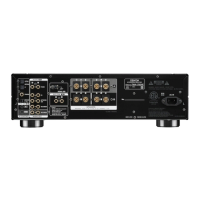
Instructions and diagrams for connecting various audio components to the amplifier.

Panel Controls and Operation

Control Descriptions

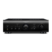
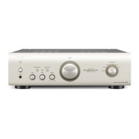
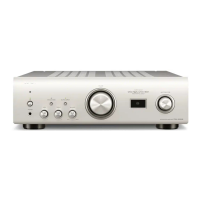
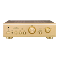
Explanations of the functions of each amplifier panel control and indicator.

Remote Control Unit Operation

Technical Specifications

Service Information

Block and Level Diagram

Diagram illustrating signal flow, levels, and internal structure of the amplifier.

Adjustment Procedures

Detailed steps for setting idling current and other critical adjustments.

Unit Disassembly

Exploded View

Wiring Diagram

Schematic Diagrams

Circuit Diagrams by Unit

Detailed schematic diagrams for EQ, Control, Protector, and µ-COM units.

Model Connection Schematics

Schematics showing connection differences for various models and HP units.

Related product manuals