EasyManua.ls Logo

Denon PMA-1315R Service Manual

Denon PMA-1315R
28 pages
To Next Page IconTo Next Page
Page #1 background imageLoading...
Page #1 background image
[)
E
N
OC
N
Hi-Fi
Integrated
Stereo
Amplifier
SERVICE
MANUAL
MODEL
PMA-131
5R
MODEL
PMA-1315RG
INTEGRATED
STEREO
AMPLIFIER
The
photograph
shows
the
PMA-1315RG
with side
wood
boards.
(Multi-Voltage
Model
only}
CONTENTS
|
OPERATING
INSTRUCTIONS
..
02.
c
cee
cet
ee
eee
teen
eee
eee tee
eres
‘asad
eae
2-7
REMOVAL
OF
EACH
SECTION
..........-
See
sia
he
to
eee
Seabee
osu
8,9
|
FUNCTION
OF
NEW
CIRCUIT
20.0.2.
c
cece
eee
cence
teen
etn
e
entree
seen
eaten
ence
10,11.
METHOD
OF
ADJUSTMENTS
.....-....
Se
humeekins
Diep
lua
eedee
ohne
aa
iupet
sey:
pioawoulehas
12
BLOCK
AND.LEVEL
DIAGRAM
2.2
5.2005
00
ress cups
teers
ssaevesavn
ees
beamed
bexaaees
ates
13
SEMICONDUCTORS
......
Shien
Cacrenie
Chucnatite
ae
edna
ten
debaae
bonus
KEYS
ooeer
Enemas:
14,
15
-
PRINTED
WIRING
BOARD
.......-
NG
LSen
aD
Aaetre
ke
tea
eee
ease
Mictansidesonees
16,
17,
PRINTED
WIRING
BOARD
PARTS
LIST...
0.
cc
cece
eee
cece
seen
erence
eee
eeeenes
ee
rere
18-21.
EXPLODED
VIEW
OF
CHASSIS
AND
CABINET
..........00
02s
tree
eee
eeeee
de
via
sSausegeataie
ea
echaats
22
PARTS
LIST
OF
EXPLODED
VIEW
6020)
cdscineseuchv-sune
sans
vene
oet
iene
ead
«ined
aveeunnensene
23°
WIRING
DIAGHAM
iaSecucnnanss
so
coc
iek
tenieawesanas
ced
a
bids
nusdiretiamerearetngaadsennsees
24
SCHEMATIC
DIAGRAM
ic
esaet
cox
cake
cas
ulin
se
se
bwau
lanunaaen
votuutneuia
renee
saesse
_
NIPPON
COLUMBIA
CO.
LTD.
Question and Answer IconNeed help?

Do you have a question about the Denon PMA-1315R and is the answer not in the manual?

Denon PMA-1315R Specifications

General IconGeneral
Frequency Response5 Hz - 100 kHz (+0, -3 dB)
Weight11.8 kg
Speaker load impedance4 - 16 ohms
Power Output100 W (8 ohms, 20 Hz - 20 kHz, THD: 0.07%)
Total Harmonic Distortion0.01%
Input Sensitivity150 mV (line input)
Signal-to-Noise Ratio100 dB
Dimensions434 x 162 x 392 mm (W x H x D)

Summary

SERVICE MANUAL

SAFETY INSTRUCTIONS

General Safety Precautions

Detailed safety precautions for appliance operation and servicing.

Regional and General Cautions

Specific warnings for US/Canada and general cautionary notes.

Installation Precautions and Usage Notes

Installation Guidelines

Guidelines for safe installation and placement of the unit.

General Usage Notes

Tips on handling, ventilation, and environmental considerations.

Unit Connections and Layout

Panel Identification

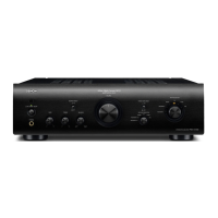
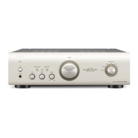
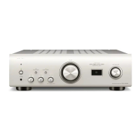
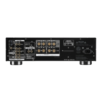
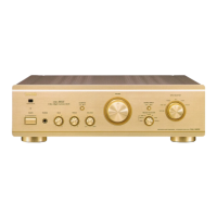
Labels for front/rear panels and diagrams of connections.

Connection Examples

Diagrams illustrating how to connect speakers and audio equipment.

Panel Controls and Functions

Power, Indicators, and Audio Controls

Functions of power switch, LEDs, Bass, Treble, Balance, Loudness.

Input/Output Selection and Sensors

Functions of Input Selector, Rec Out Selector, PHONES, SPEAKERS, REMOTE SENSOR.

Remote Control Operation

Battery Usage and Installation

Guide to inserting and maintaining batteries for the remote control.

Remote Control Button Functions

Explains operation of power, muting, and other buttons on the remote.

Technical Specifications

Amplifier and Pre-Amplifier Specs

Details on output power, distortion, input sensitivity, SN ratio.

General Characteristics and Remote Unit

Tone control ranges, dimensions, weight, remote unit details.

Unit Disassembly Procedures

Top Cover and Main Chassis Removal

Instructions for removing the top cover and main chassis.

Front Panel and Internal Component Removal

Front Panel Disassembly

Steps to remove the front panel and its associated parts.

Inner Panel and P.W. Board Removal

Procedures for detaching the inner panel and PW board.

New Circuit Functions

Bias Control Circuit Characteristics

Explains the purpose and function of the bias control circuit.

Bias Control Circuit Block Diagram

Visual representation of the bias control circuit's functional blocks.

Control Circuit Power Supply

Details on the power supply needed for the bias control circuit.

IC Description and Circuit Details

IC Pin Function Descriptions

Details the pin functions for the µPC5023CS-064 IC.

Detailed Circuit Implementation

Shows the concrete circuit implementation of the bias control system.

Method of Adjustments

Idling Current Adjustment

Steps for setting up and adjusting the idling current.

Block and Level Diagram

Semiconductor Components Identification

Integrated Circuit (IC) Details

Lists ICs like µPC5023CS-064 and HD404304A13P.

Transistor, Diode, and LED Identification

Transistor Identification

Lists and identifies various transistors used in the unit.

Diode, LED, and Thyristor Identification

Details on diodes, LEDs, thyristors, and optocouplers.

Printed Wiring Board Layout

Printed Wiring Board Parts List

Semiconductor Parts List

List of semiconductors with part numbers and specifications.

Resistor and Capacitor Parts Lists

Lists of resistors and capacitors with their characteristics.

Additional Parts Lists

Other Group Parts List

Lists parts not categorized elsewhere, like connectors.

Model-Specific Parts Lists

Parts lists for different model variations (Europe, USA/Canada).

Exploded View of Chassis and Cabinet

Exploded View Parts Identification

Exploded View Component List

Lists all components shown in the exploded view.

Addendum Parts List

Supplemental list of parts not covered in the main exploded view list.

WIRING DIAGRAM

SCHEMATIC DIAGRAMS

Related product manuals