5
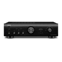
PMA-710AE
DISASSEMBLY
• Disassemble in order of the arrow of the figure of following flow.
• In the case of the re-assembling, assemble it in order of the reverse of the following flow.
• In the case of the re-assembling, observe "attention of assembling" it.
About the photos used for descriptions in the “DISASSEMBLY” section.
• The direction from which the photographs used herein were photographed is indicated at "Direction of photograph: ***" at
the left of the respective photographs.
• Refer to the table below for a description of the direction in which the photos were taken.
• Photographs for which no direction is indicated were taken from above the product.
TOP CABINET
FRONT PANEL ASSY POWER PCB REAR PANEL
Refer to "DISASSEMBLY 1.FRONT PANEL ASSY" Refer to "EXPLODED VIEW" Refer to "EXPLODED VIEW"
and "EXPLODED VIEW" POWER PCB
FRONT PCB (Ref. No. of EXPLODED VIEW : 1-2)
(Ref. No. of EXPLODED VIEW : 2-1)
MAIN PCB ASSY
FUNCTION PCB Refer to "EXPLODED VIEW"
(Ref. No. of EXPLODED VIEW : 2-3)
POWER TRANSFORMER
MAIN PCB ASSY
VOLUME PCB Refer to "EXPLODED VIEW" (Ref. No. of EXPLODED VIEW : 1-1)
(Ref. No. of EXPLODED VIEW : 2-4) POWER TRANSFORMER MCU PCB ASSY
SW/HP PCB (Ref. No. of EXPLODED VIEW : 28) (Ref. No. of EXPLODED VIEW : 2-2)
(Ref. No. of EXPLODED VIEW : 2-5)