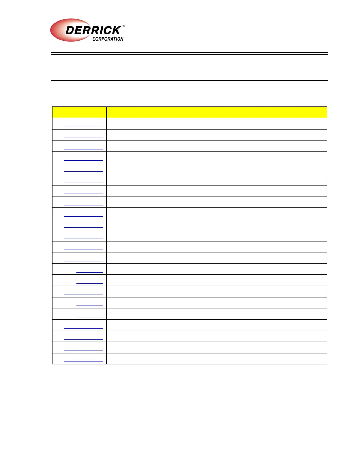
SECTION 8 - REFERENCE DRAWINGS
01 Sep 11 1-1
DE-7200VFDCentrifuge
This section contains Derrick engineering drawings for your equipment. These drawings are
included to provide assistance in troubleshooting, repair, and parts ordering.
Number
Title
16590-00-003
General Arrangement - XP Centrifuge
16590-00-004
General Arrangement - Non-XP Centrifuge
16601-00-001
Base Parts List
16602-00-001
Case and Cover Parts List
16603-00-001
Bowl Parts List
16604-00-001
Conveyor Parts List
16605-00-001
Belt Guard Parts List
14394-00-007
Electrical Wiring Schematic - 460/480V 60 Hz Non-XP Centrifuge
14394-00-009
Electrical Wiring Schematic - 460/480V 60 Hz XP Centrifuge
14394-00-011
Electrical Wiring Schematic - 380/400V 50Hz XP Centrifuge
14394-00-012
Electrical Wiring Schematic - 575/600V 60 Hz XP Centrifuge
14394-00-013
Electrical Wiring Schematic - 380/400V 50Hz Non-XP Centrifuge
16606-00-001
Feed Component Assembly
16618-00
Junction Box Assembly
16621-00
Drive Components Parts List
16593-00-002
Base Sensor System Parts List
16798-00
Repair Tool Kit
16607-00
XP Electrical Control Panel
16472-00-002
Control Enclosure Assembly, 460/480V 60 Hz XP Centrifuge
16472-00-003
Control Enclosure Assembly, 380/400V 50 Hz XP Centrifuge
16472-00-004
Control Enclosure Assembly, 575/600V 60 Hz XP Centrifuge
16472-00-005
Control Enclosure Assembly, 460/480V 60Hz Non XP Centrifuge