www.desatech.com
111986-01F20
11. Peel off backing paper and stick supplied
wiring diagram decal on rebox bottom
approximately 12" in front of blower (see
Figure 27, page 19).
-
FIREPLACE
INSTALLATION
Continued
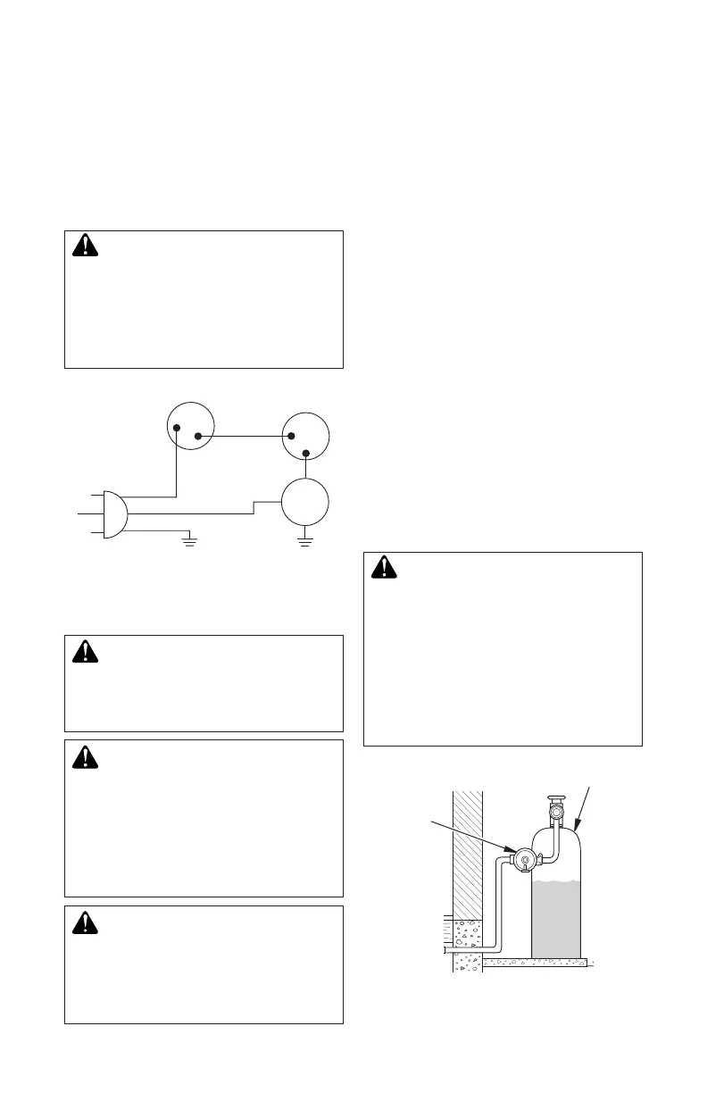
Figure 29 - Blower Wiring Diagram for
Thermostat-Controlled Models
Blue
V a riable
Fan Switch
Fan Switch
(N.O.)
Green
White
On
1 1 0/115
V. A.C.
Blower
Motor
Black
Off
1
2
Black
INSTALLING GAS PIPING TO
FIREPLACE LOCATION
WARNING: For natural
Installation Items Needed
Before installing replace, make sure you have
the items listed below.
• external regulator (supplied by installer)
• piping (check local codes)
• sealant (resistant to propane/LP gas)
• equipment shutoff valve *
• test gauge connection *
• sediment trap
• tee joint
• pipe wrench
• approved exible gas line with gas connec-
tor (if allowed by local codes)
* A CSA design-certied equipment shutoff
valve with 1/8" NPT tap is an acceptable alter-
native to test gauge connection. Purchase the
CSA design-certied equipment shutoff valve
from your retailer.
For propane/LP connection only, the installer
must supply an external regulator. The ex-
ternal regulator will reduce incoming gas
pressure. You must reduce incoming gas
pressure to between 11" and 14" of water. If
you do not reduce incoming gas pressure,
replace regulator damage could occur. Install
external regulator with the vent pointing down
as shown in Figure 30. Pointing the vent down
protects it from freezing rain or sleet.
CAUTION: Use only new,
-
-
Figure 30 - External Regulator with Vent
Pointing Down (Propane/LP Only)
Propane/LP
Supply Tank
External
Regulator
with Vent
Pointing
Down