95-8556
11. 3
12
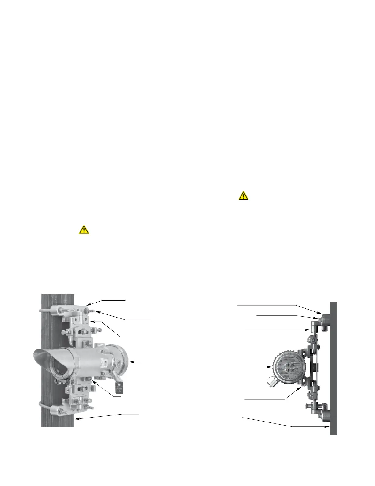
Mounting Sequence
1. Attach the OPECL module to the pan-tilt mounting
plate and tighten the OPECL mounting bolts to 20
lb.-ft. minimum.
2. Install the lower mounting bracket.
3. Place the pan-tilt mounting plate on the lower
bracket and install the upper mounting bracket.
Tighten the mounting hardware to 20 lb.-ft. minimum.
Tighten the alignment bolts/nuts hand tight only.
NOTE
Anti‑seize material (provided) must be applied to the
U‑bolt threads at the time of installation to prevent galling.
24 VDC POWER SUPPLY REQUIREMENTS
Calculate the total gas detection system power consumption
rate in watts from cold start-up. Select a power supply with
adequate capability for the calculated load. Ensure that
the selected power supply provides regulated and filtered
24 Vdc power for the entire system. If a back-up power
system is required, a float-type battery charging system is
recommended. If an existing source of 24 Vdc power is being
utilized, verify that system requirements are met.
NOTE
If disconnection of power is required, separate
disconnect capability must be provided.
WARNING
All entries must contain appropriately rated plugs
or ttings. It is required that each plug or tting be
wrench‑tightened to an appropriate installation
torque and meet the minimum thread engagement
requirements per the applicable local standards, codes,
and practices in order to retain the defined ratings.
PTFE sealant or equivalent should be used on NPT
threads.
IMPORTANT
Devices certied for hazardous locations shall be
installed in accordance with EN/IEC 60079‑14 and
NEC 505.
WIRING CABLE REQUIREMENTS
Always use proper cabling type and diameter for input
power as well as output signal wiring. 14 to 18 AWG
shielded stranded copper wire is recommended. For
EQP models, refer to the EQP system manual (95-8533)
for specific wiring requirements and recommendations.
Always install a properly sized master power fuse or
breaker on the system power circuit.
NOTE
The use of shielded cable in conduit or shielded
armored cable is required for ATEX conformance.
In applications where the wiring is installed in
conduit, dedicated conduit is recommended. Avoid
low frequency, high voltage, and non‑signaling
conductors to prevent nuisance EMI problems.
CAUTION
The use of proper conduit installation techniques,
breathers, glands, and seals is required to prevent water
ingress and/or maintain the explosion‑proof rating.
MOUNTING BRACKET (2)
U-BOLT* (2)
PAN-TILT MOUNTING PLATE
OPECL MODULE
OPECL MOUNTING BOLT (2)
MOUNTING POST
B2305
*APPLY ANTI-SEIZE MATERIAL TO U-BOLT
THREADS TO PREVENT GALLING.
Figure 5—OPECL Gas Detector Mounted to Vertical Post
MOUNTING BRACKET (2)
MOUNTING BOLT (2 PER BRACKET)
PAN-TILT MOUNTING PLATE
OPECL MODULE
OPECL MOUNTING BOLT (2)
FLAT MOUNTING SURFACE
A2306
Figure 6—OPECL Gas Detector Mounted to Flat Surface