rent output during this period is 0 milliamperes. At the
end of the warmup period with no faults present, the
detector automatically enters the Normal operating
mode. If a fault is present after the warmup, the detec-
tor current output will indicate a fault.
Normal
In the normal operating mode, the 4 to 20 milliampere
signal level corresponds to the detected gas concentra-
tion. The detector continuously checks for system faults
or initiation of calibration, and automatically changes to
the appropriate mode.
Fault
Faults detected during warmup, normal operation, or
calibration are indicated by the current loop output as
shown in Table 1.
Calibration
When the calibration lead is momentarily connected to
the negative lead (common) of the power supply, the
microprocessor executes the zero and span calibration
sequence. The output current during calibration
defaults to an inhibited state. See Table 1.
NOTE
The current output during calibration can be set for
live operation, however, this method is not usually
recommended. Refer to the “Calibration” section
for further information.
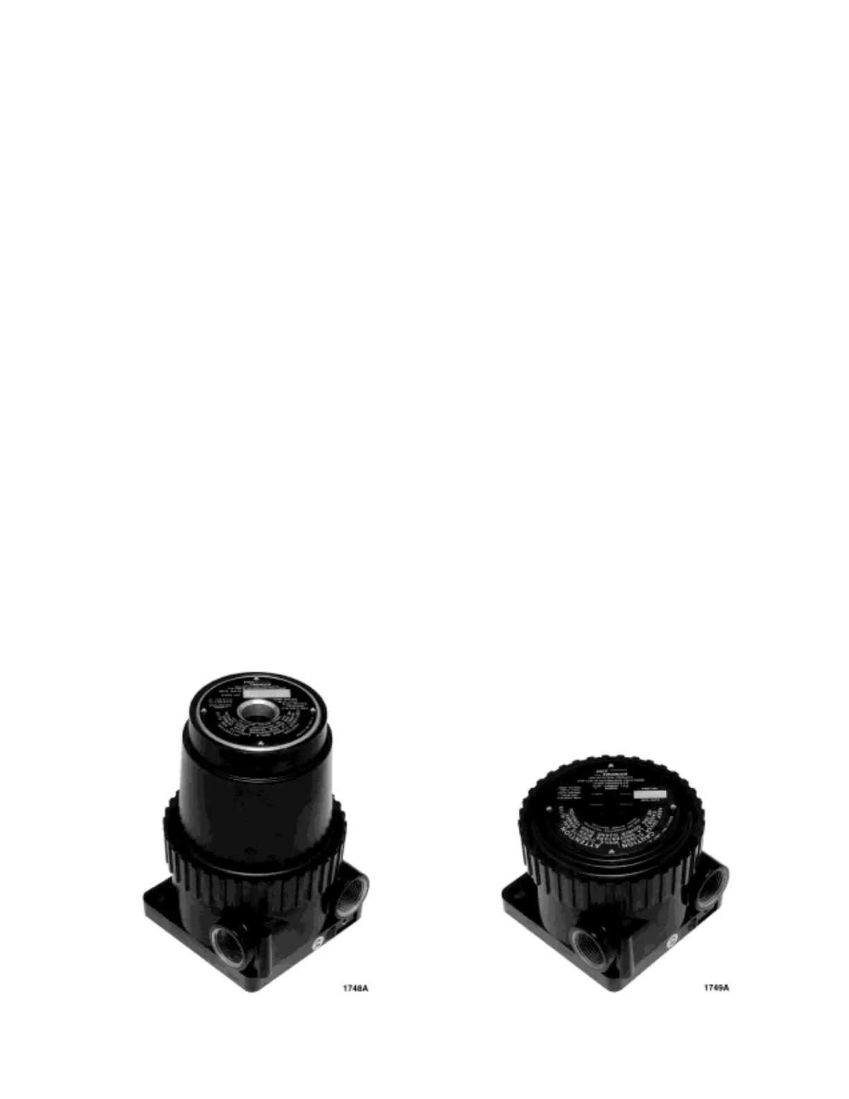
Two junction box types for use specifically with the
PointWatch detector are available from Det-Tronics.
• Tall Cover/Window Junction Box for one person,
non-intrusive calibration. This junction box includes
a magnetic reed calibration switch, calibration LED
and a windowed cover. Activating the magnetic
reed switch with the calibration magnet and viewing
the LED through the window provides one person,
non-intrusive calibration capability. See Figure 6.
• Short Cover Junction Box for PointWatch requires
two people to accomplish non-intrusive calibration.
This junction box includes a magnetic reed calibra-
tion switch, calibration LED and a solid cover.
Activating the magnetic reed calibration switch with
the calibration magnet or touching the calibration
lead to the negative lead (common) of the power
supply using an external switch are methods used
to initiate calibration. This junction box can also be
used for sensor separation. See Figure 7.
INSTALLATION
IMPORTANT
Hydrocarbon-based grease will emit hydrocarbon
vapors which will be measured by PointWatch and
will result in inaccurate gas level readings. Use
only low vapor pressure silicone grease when
lubricating threads on the PointWatch detector
and associated junction box. Do not get this
grease on the optics of the detector. A suitable
grease is listed in the “Spare Parts” section at the
end of this manual.
IMPORTANT
In applications where both PointWatch and catalyt-
ic type sensors are used, ensure that the silicone
grease used to lubricate the PointWatch detector
threads does not come into contact with the cat-
alytic sensors or poisoning of the catalytic sensors
will result. It is strongly recommended that mainte-
nance personnel wash their hands between han-
dling the two types of sensors.
5 95-8440
Figure 6—Tall PointWatch Junction Box with Window
Figure 7—Short PointWatch Junction Box