DETECTOR LOCATION
It is essential that the device be properly located to
enable it to provide maximum protection. The most
effective number and placement of sensors varies
depending on the conditions at the job site. The indi-
vidual designing the installation must rely on experience
and common sense to determine the type and quantity
of sensors and the best sensor locations to adequately
protect the area. The following factors should be con-
sidered for every installation:
1. What kind of gas is to be detected? If it is lighter
than air, place the sensor above the potential gas
leak. Place the sensor close to the floor for gases
that are heavier than air or for vapors resulting from
flammable liquid spills. However, note that air cur-
rents can cause a gas that is heavier than air to
rise. In addition, if the gas is hotter than ambient air
or mixed with gases that are lighter than air, it could
also rise.
2. How rapidly will the gas diffuse into the air? Select
a location for the sensor as close as practical to the
anticipated source of a gas leak.
3. Ventilation characteristics of the immediate area
must also be considered. Movement of air may
cause gas to accumulate more heavily in one area
than another. The detector should be placed in the
areas where the most concentrated accumulation of
gas is anticipated. Also take into consideration the
fact that many ventilation systems do not operate
continuously.
4. Proper orientation is dependent upon the
PointWatch model used and the environmental con-
cerns at the installation. See Table 2.
5. The sensor should be accessible for maintenance.
6. Excessive heat or vibration can result in premature
failure of any electronic device and should be
avoided if possible.
NOTE
For additional information on determining the quan-
tity and placement of gas detectors in a specific
application, refer to the article titled “The Use of
Combustible Detectors in Protecting Facilities from
Flammable Hazards” contained in the Instrument
Society of America (ISA) Transaction, Volume 20,
Number 2.
0 TO 100% LFL LINEARIZED OUTPUT OPTIONS
The PointWatch detector is factory configured for 0 to
100% LFL methane. This configuration can be changed
to other gases in the field by changing the setting on the
rotary gas selection switch, which is located on the
electronics module, and calibrating the device with the
new standard gas selected.
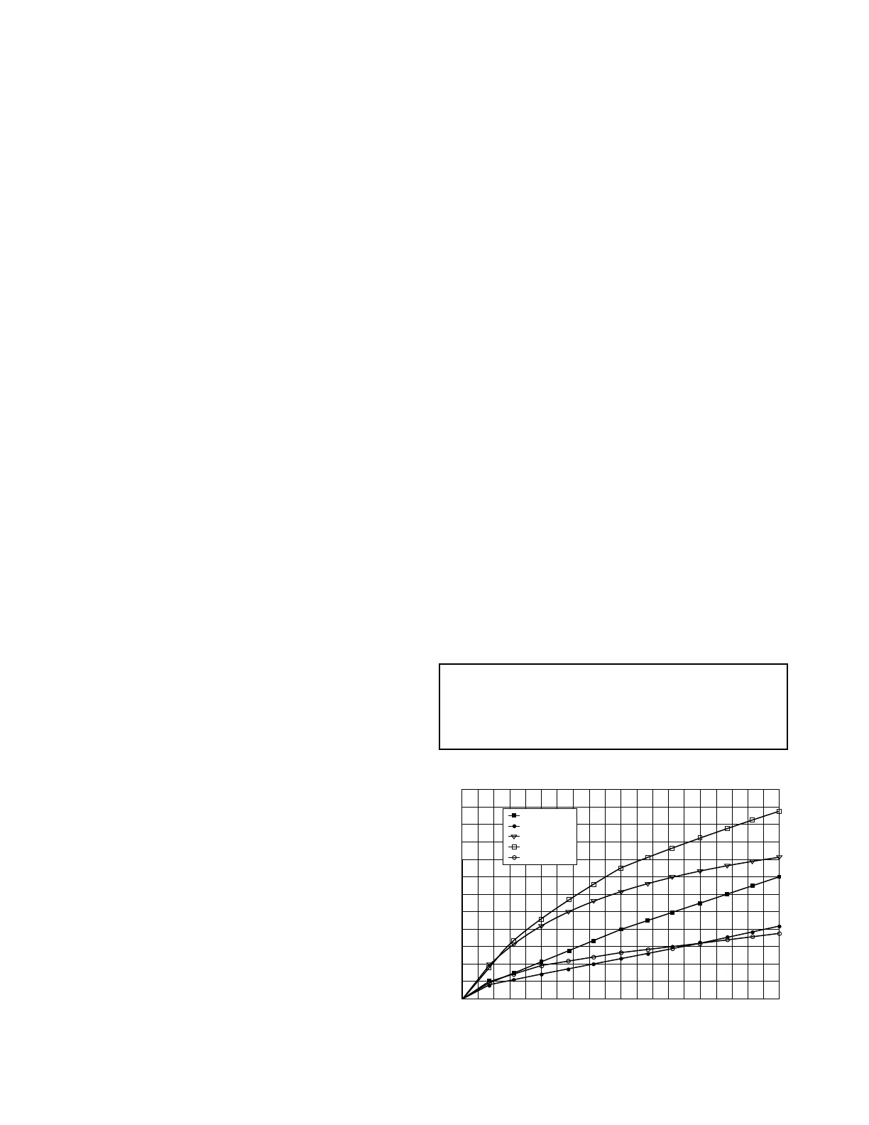
PointWatch has a good response to hydrocarbon gases
and to the vapors of hydrocarbon liquids. However, the
response varies depending on the structure of the
hydrocarbon molecule (see Figure 8). The raw
response of PointWatch is linearized to provide a 0 to
100% LFL output for five standard gases: methane,
ethane, propane/butane, ethylene, propylene.
Changing Linearized Output Gas Selection
IMPORTANT
Remove power before removing and disassem-
bling the PointWatch detector.
1. Loosen the two captive screws on the flat end of the
detector and slide the filter assemblies off. For the
aluminum model, use a standard screwdriver. For
the stainless steel model, use a 7/64 inch hex driv-
er. See Figure 9 (aluminum) or Figure 10 (stainless
steel).
2. Unscrew and remove the electronics mounting
cover by rotating it counter-clockwise. See Figure
11.
3. Slide the electronics mounting cover back to the
base of the mirror assembly and pull the IR module
out of the base as shown in Figure 12.
6
Figure 8—PointWatch Gas Absorption Curves
 Loading...