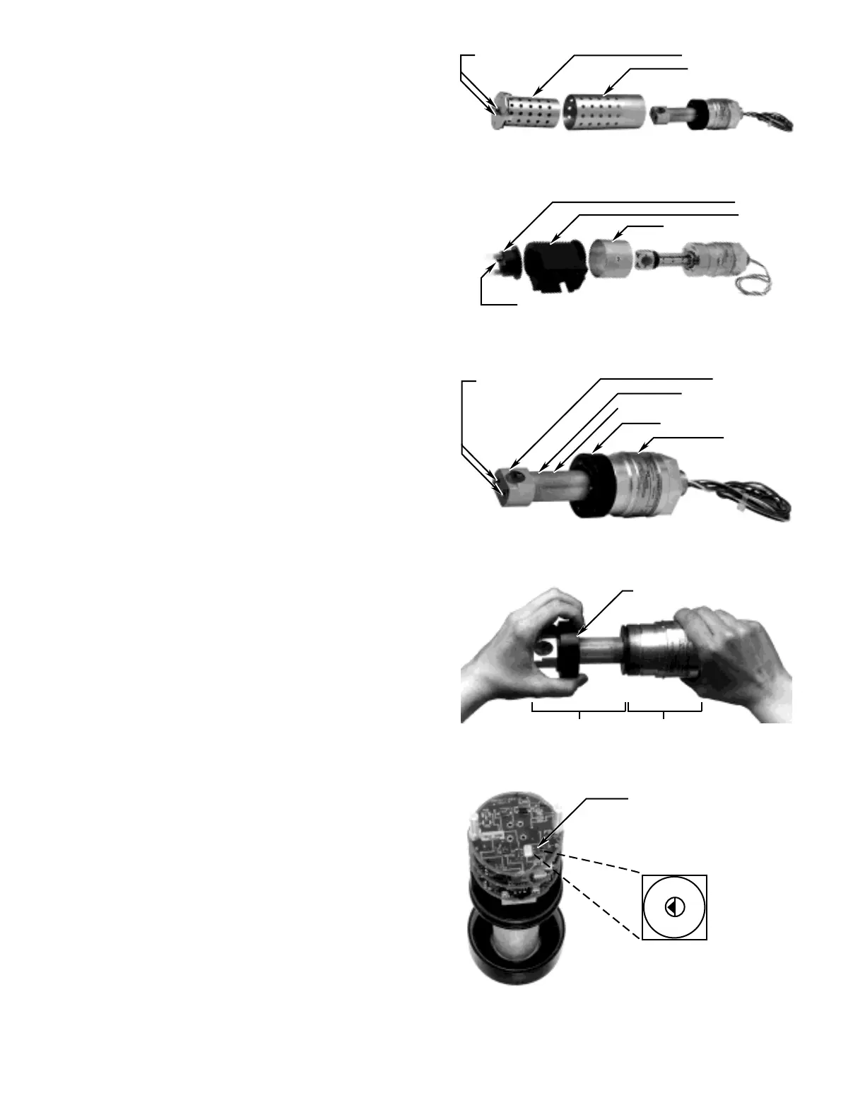
4. Using a small screwdriver, rotate the gas selection
switch from position 0 (methane) to the desired
position. Refer to Figure 13. Ensure that the tip of
the arrow on the switch lines up with the position
selected.
5. The module is “keyed” using different sized pins on
the bottom of the module. Slide the IR module into
the base and rotate it until the keyed holes are
aligned, then press securely into place.
NOTE
This assembly fits correctly only in one orientation.
If it is not seating into place, rotate it 180° and try
again.
6. Screw the electronics mounting cover clockwise
onto the base assembly as shown in Figure 11.
7. For the aluminum model, slide the outer filter
assembly over the mirror assembly. The outer filter
should be oriented with the solid portion toward the
base of the unit. If it is not oriented correctly, the fil-
ter assembly will not slide onto the unit. Slide the
inner filter assembly into the outer filter assembly
and rotate until it is seated securely, then fasten the
two captive screws using a standard screwdriver.
See Figure 9.
For the stainless steel model, slide the stainless
steel collar onto the base assembly, then slide the
baffle onto the unit. Place the end cap on the baffle
and rotate it until it is seated securely, then fasten
the two captive screws using a 7/64 inch hex driver.
See Figure 10.
8. Calibrate the detector with 50% LFL of the gas that
matches the calibration gas switch position follow-
ing the instructions in the “Calibration” section of
this manual.
JUNCTION BOXES
The PointWatch detector is designed to be threaded
into a junction box, which can be mounted to a solid,
vibration free wall or post. A 3/8 inch spacer may be
required between the enclosure and the mounting sur-
face to allow adequate room for the sensor and calibra-
tion accessory.
Intrusive and Non-Intrusive Calibration
For hazardous locations, it is important to consider the
options for calibration of PointWatch. The device can
be installed so that calibration can be performed by one
person without opening the explosion-proof enclosure
(non-intrusive calibration). This is accomplished by
incorporating a display or LED that provides information
 Loading...