700 RAM I.M.
700 RAM I.M. iii
Table of Contents
1. Introduction ..................................................................................................................................................1
1.1 Description.......................................................................................................................................... 1
1.2 Installation........................................................................................................................................... 1
1.3 Field Wiring........................................................................................................................................ 3
2. Operator Interface.........................................................................................................................................5
3. Set-up and Normal Operation.......................................................................................................................7
3.1 View Sensor Status............................................................................................................................. 8
3.2 Set AutoSpan Level ............................................................................................................................ 8
3.3 Set Serial ID........................................................................................................................................ 9
3.4 Set-up for Relay Outputs .................................................................................................................... 9
3.5 Signal Output Check......................................................................................................................... 10
4. RS-485 Modbus
™
Protocol.........................................................................................................................11
5. RAM Electronics Warranty........................................................................................................................11
6. Specifications .............................................................................................................................................12
6.1 Spare Parts ........................................................................................................................................ 12
6.2 Revision Log......................................................................................Error! Bookmark not defined.
Table of Figures
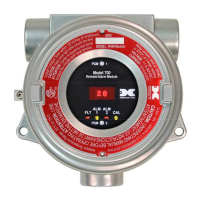
Figure 1 700 RAM ............................................................................................................................................... 1
Figure 2 RAM Mounting...................................................................................................................................... 2
Figure 3 Mounting RAM with 700 Sensor........................................................................................................... 2
Figure 4 Exploded View of Assembly ................................................................................................................. 3
Figure 5 Interface connections on terminal board................................................................................................ 3
Figure 6 Installation with 700 Gas Sensor ........................................................................................................... 4
Figure 7 Remote 700 Gas Sensor with RAM....................................................................................................... 4
Figure 8 RAM Software Flowchart...................................................................................................................... 7