700 RAM I.M.
700 RAM I.M. Rev. 1.1 Page 5 of 12
(+)
mA
(-)
A(+)
B(-)
Wiring to
Sensor Assembly
Wht
Blu
Red
Grn
Blk
Remote
Explosion Proof
Junction Box
with Sensor
(+)
mA
(-)
A(+)
B(-)
Customer
Supplied Wiring
Transient Protection Module
(TPM) P/N 500-003087-100
Modbus RS-485 to
Host Control Device
Power from and 4-20mA
out to Control Device
ALM1ALM2 FLT
NO NC COM NO NC COM NO NC COM
J7
J2
J1
J4
IN
SENSOR
OUT
+
+
mA
A B
mA
A
B +
A
B
K1
K3
K2
Explosion Proof
Junction Box
with RAM Module
(+)
mA
(-)
A(+)
B(-)
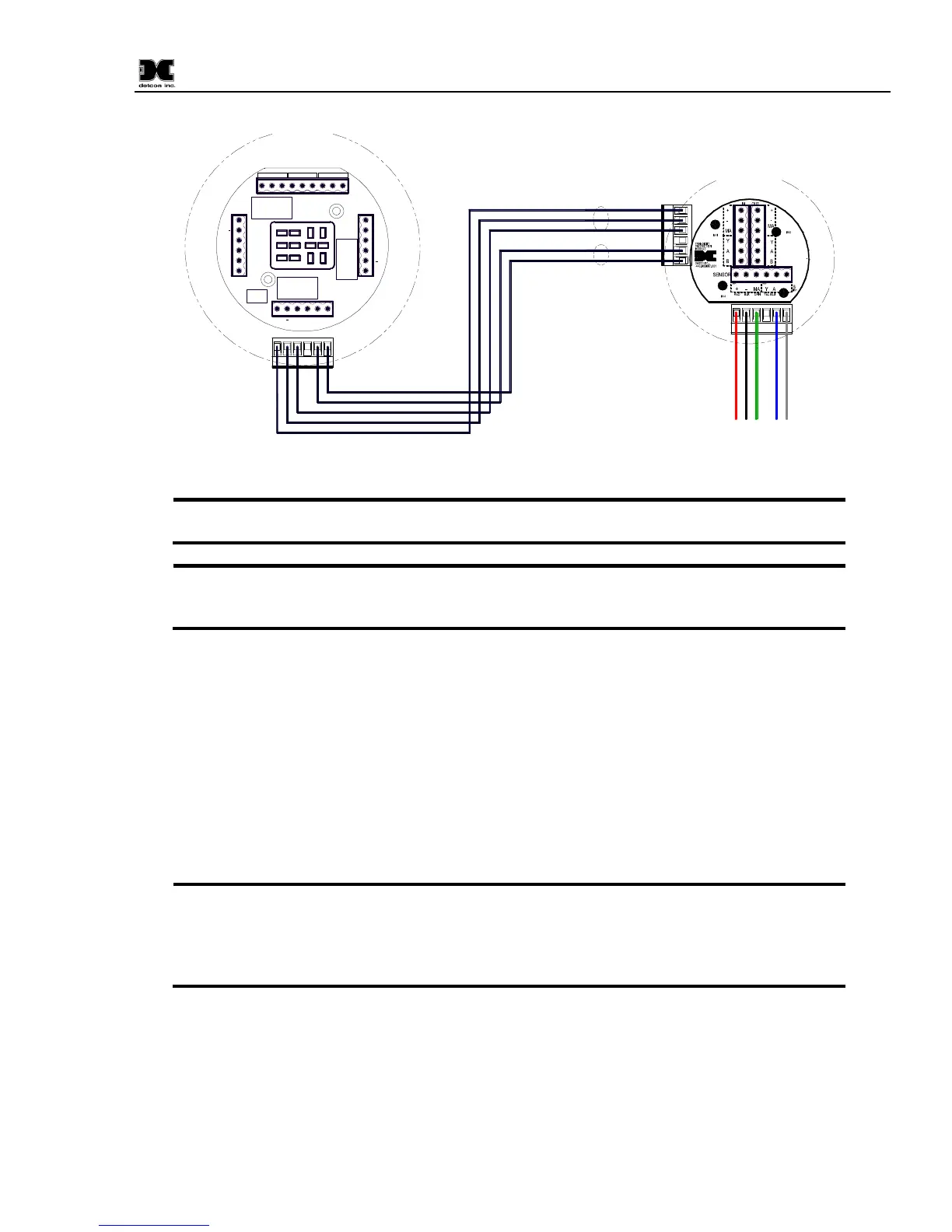
Figure 8 Remote Sensor Wiring
Both the 3-wire power/mA cable and the 2-wire Modbus™ serial communications
cable are required when remote wiring between the RAM and the 700 Gas Sensor.
The same recommended cables should be used for the connection between a
Modbus™ master control device and the RAM. However, if only the 4-20mA signal is being
used by the master/host controller, then only the 3-wire cable is required.
2. Operator Interface
The operator interface of the RAM is very similar to the Model 700 Gas Sensor. It uses the identical LED
display, same programming magnet, and has the same magnetic programming switches (PGM1/ZERO and
PGM2/SPAN). The main difference is that the 700 RAM has LED indicators for the 3 relays (ALM1,
ALM2 and FAULT) and a CAL LED to indicate when the 700 sensor is in calibration or being polled
serially by a master control device.
The gas reading, gas units, and fault status reported by the RAM will mimic that of the 700 Gas Sensor. The
Modbus™ output from the RAM repeats the Modbus™ output from the 700 Gas Sensor.
If the Model 700 Gas Sensor is directly connected to the RAM and junction box, then
the gas sensor operation should be exercised through the 700 Gas Sensor (and not the RAM).
This is the recommended practice since the RAM contains a limited number of sensor
operational control functions. If the RAM and 700 Gas Sensor are separated, then normal
remote gas sensor operation should be exercised through the RAM.
The operating interface is menu-driven via the two magnetic program switches located under the target
marks on the RAM faceplate. The two switches are referred to as “PGM1” and “PGM2”. The menu list
consists of three major items that include sub-menus as indicated below. (Refer to the complete Software
Flow Chart Figure 9)
Normal Operation
Current Reading and Fault Status