700 RAM I.M.
700 RAM I.M. Rev. 1.1 Page 1 of 12
1. Introduction
1.1 Description
The Model 700 Remote Sensor/Alarm Relay Module (known as the Remote Alarm Module or RAM) is sold
separately as an accessory for Model 700 Gas Sensors. It is a universal design and can be used with any of
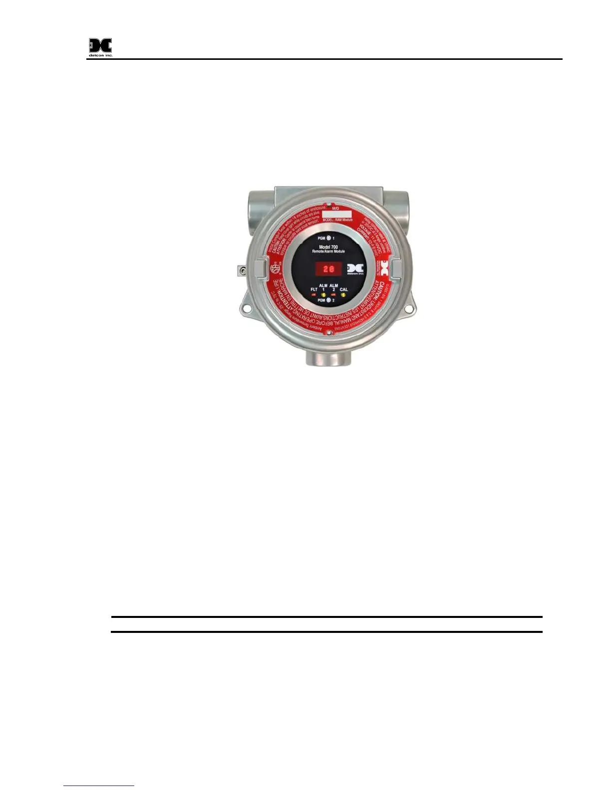
the Model 700 Gas Sensors. The RAM is provided in an explosion-proof junction box constructed of either
epoxy-painted aluminum (Figure 1) or 316 stainless steel and includes a glass-viewing window.
Figure 1 700 RAM
The RAM performs two main functions. The first function is to set gas alarm levels and to configure the
three local relay contacts. The second function is to operate a Model 700 Gas Sensor remotely. The remote
sensor function is typically used when the sensor must be mounted in a position where it cannot be viewed or
accessed readily. Both functions can be used at the same time.
The RAM provides the 4-20mA output directly from the Model 700 Gas Sensor. The RAM acts as a
Modbus™ master to the Model 700 Gas Sensor in order to display the reading and execute the remote
control functions. It acts as a Modbus™ slave to any master control device and simply repeats the
Modbus™ output from the 700 Gas Sensor it is connected to.
1.2 Installation
The RAM can be installed as a wall mount or pipe mount using the mounting holes of the explosion-proof
junction box. It should be oriented such that the LED display is horizontal. If the 700 Gas Sensor is
mounted directly to the RAM, use 0.5” spacers underneath the mounting holes to provide access clearance
for the 700 Gas Sensor (Figure 3).
Block any unused ¾” NPT holes with the proper Plug. (Detcon P/N 8522-750)