Do you have a question about the Detroit Diesel DDEC VI and is the answer not in the manual?
Use safety stands with hydraulic jacks or hoists; do not rely on jack or hoist to carry load.
Select and wear appropriate safety glasses when using tools like hammers, chisels, pullers, and punches.
Take precautions to avoid damage to electronic controls and engine when welding.
Improper use of electrical equipment can cause severe injury; follow operating instructions.
Fluids under pressure can penetrate skin; do not put hands in front of fluid under pressure.
Work in a well-ventilated area, wear protective clothing, and avoid sparks near batteries to prevent explosion.
Keep a charged fire extinguisher within reach and ensure it is the correct type for the situation.
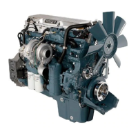
The engine-mounted MCM includes control logic for overall engine management.
The Aftertreatment Device (ATD) configuration includes DOC and DPF, with wiring determined by ATD mount position.
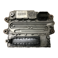
The CPC interfaces MCM with vehicle/equipment for engine control and manages other functions.
The OEM-supplied VIH connects the CPC to MCM and other vehicle systems.
Covers Deutsch terminal installation and removal methods, including proper tools and procedures.
Provides guidelines for splices, recommending clipped and soldered splices for most circuits.
DDEC operates with several sensor types including Variable Reluctance, Thermistor, and Switches.
Provides input to engine protection system and warns of low coolant level.
CPC calculates vehicle speed using VSS; signal type can be changed.
AWL is controlled by DDEC VI and indicates system faults or specific conditions.
RSL is controlled by DDEC VI and indicates potential engine damaging faults.
Informs operator when parked regeneration is required; solid illumination for manual regeneration.
Indicates emission-related faults; illuminated when fault is active, goes out when inactive.
Lists input functions and their associated CPC connector pins.
Switches for adjusting set speed and resuming cruise control.
Allows flashing of diagnostic codes using AWL and RSL; momentary normally open switch.
Input switched to ground to prevent engine braking when traction control is active.
Inputs indicate engine is being limited to torque, engine speed, or vehicle speed.
Used by operator to initiate parked regeneration; momentary normally open switch.
Momentary switch to enable shutdown override; records override activations.
Supports multiplexing of several switch inputs over the SAE J1939 Data Link.
Lists CPC digital output functions, driver types (low/high side), and associated pins.
Illuminated for active faults and flashes during engine shutdown; REQUIRED output.
Informs operator when parked regeneration is required; optional function.
Required amber warning lamp for emission-related faults.
Flashes while timer counts down, illuminates steadily when Optimized Idle is active; REQUIRED for OI.
Switches to sensor return to turn on Optimized Idle Alarm; REQUIRED for OI.
Illuminated for serious faults requiring immediate shutdown; REQUIRED output.
Drives a normally closed relay to interrupt starting signal when output is activated.
Actuates relay to shut down electrical power when engine is shutdown.
Maintains targeted speed (MPH) by adjusting fueling; requires VSS or output shaft speed message.
Provides information for problem identification and solving via codes; MCM/CPC perform self-diagnostics.
Converts engine into power-absorbing compressor; operations allowed under specific conditions.
Controls engine brake solenoids and VGT position for low, medium, or high braking power.
Monitors engine sensors and components; illuminates AWL/RSL for critical faults and logs codes.
Shuts down engine if idling for a specified period; options include override, power shutdown, PTO.
Reduces engine idle time by stopping/restarting engine based on conditions like battery charge and temp.
| Engine Type | Diesel |
|---|---|
| Power Output | 350-600 hp |
| Torque | 1250-2050 lb-ft |
| Fuel System | High-pressure common rail |
| Aspiration | Turbocharged and aftercooled |
| Number of Cylinders | 6 |
| Governor Type | Electronic |
| Oil System | Wet sump |
| Communication Protocol | J1939 |
| Control System | DDEC VI (Detroit Diesel Electronic Controls) |
| Emissions Compliance | EPA 2007 |
| Weight | Varies depending on model |
| Cylinder Configuration | Inline |
| Cooling System | Liquid-cooled |
| Configuration | Inline |