Do you have a question about the Dettson CHINOOK CC15-M-V and is the answer not in the manual?
Explains DANGER, WARNING, CAUTION levels and their meanings.
Provides crucial safety and operational advice for users and installers.
Critical warnings regarding personal injury, death, and property damage.
Warning about sharp sheet metal parts and the need for protective gear.
Risks and precautions related to CO poisoning from furnace operation.
Specific warnings for installing the furnace in a residential garage.
Essential steps to ensure correct and safe venting of the furnace.
Recommends installing CO and smoke detectors for safety.
Warns of frozen pipes and property damage risks.
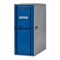
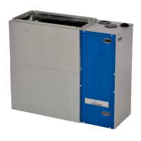
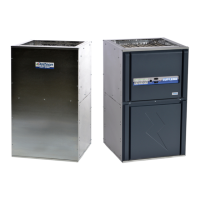
Introduces the furnace type and general installation compliance.
Lists US and Canadian safety codes for furnace installation.
Specifies general installation standards and codes.
Codes pertaining to air supply and ventilation for combustion.
Standards for designing and sizing duct systems.
Standards for duct lining and fibrous glass materials.
Codes governing gas piping installation and leak testing.
Standards for making electrical connections.
Steps to prevent damage to electronic controls from static discharge.
Specifies location requirements for furnace installation.
Placement considerations when a cooling coil is present.
Details on using the thermostat with the Alizé cooling system.
Instructions on locating the furnace interface board.
Explains how to wire the interface board to furnace controls.
Step-by-step guide for connecting condensate drain in upflow.
Connecting the condensate drain for downflow orientation.
Guide for connecting condensate drain in horizontal setup.
Ensures correct drainage for horizontal exhaust vent piping.
Connects the multiposition pressure switch to furnace control.
Design and sizing requirements for duct systems.
Information on the Dettson Smart Duct System.
Guidelines for connecting return air ducts to the furnace.
Requirements for connecting supply air ducts.
Methods for acoustical treatment of ductwork.
General procedures for gas supply and piping installation.
How to adjust and verify gas pressure settings.
Steps to convert the furnace from natural gas to propane.
Sealing the gas pipe opening on the cabinet.
Proper connection and grounding of the 120V power supply.
Guidelines for connecting 24V thermostat wiring.
Information on selecting the correct thermostat for the system.
Guidelines for using generators or other alternate power sources.
General requirements for vent and combustion air piping.
Lists approved materials for combustion air and vent pipes.
Specific rules for direct vent (2-pipe) installations.
Rules for non-direct vent (1-pipe) installations.
Specific vent termination requirements for Alberta and Saskatchewan.
Special venting regulations for installations in Canada.
Guidelines for sizing vent and combustion air pipes.
Procedures for connecting vent and air pipes to the furnace.
Steps for installing the combustion air piping.
Steps for installing the exhaust vent piping.
Procedures for correctly terminating vent pipes.
Specific instructions for installing concentric vent terminations.
Guidelines for installing two-pipe vent terminations.
Steps and prerequisites for starting the furnace.
Sequence for lighting the furnace burners.
Hazards associated with furnace operation and safety features.
How to configure the furnace's setup switches.
Explanation of codes displayed during normal furnace operation.
Steps to clear fault codes from the furnace memory.
Overview of diagnostic capabilities and error reporting.
Detailed sequence of the heating cycle.
Procedure for checking and setting the furnace input rate.
Using non-communicating thermostats for modulating operation.
Terminal connections for various thermostat inputs.
Details on the furnace control board's 3-amp fuse.
Terminals for connecting 120VAC accessories like air cleaners.
How to connect an electronic air cleaner.
Function of the HUM terminal for humidification.
How the furnace controls the stepper gas valve.
Function and pin assignments of the 15-pin connector.
Connection details for the ECM blower motor.
Understanding the RX and STAT communications LEDs.
Critical information about furnace memory cards.
Procedure for replacing the furnace control board.
Configuration of DIP switches for various functions.
Using DIP switches to adjust heating airflow.
Selecting cooling airflow based on motor HP and settings.
Using DIP switches to select heat rise settings.
Setting the continuous fan speed using DIP switches.
How to enter and operate the furnace in test mode.
Emergency procedures to follow when smelling gas.
Basic instructions for operating the furnace.
Steps for lighting the furnace burners.
Explains fault code D1 related to missing shared data.
Explains fault code D4 for corrupt or missing memory card.
Explains fault code D5 for an incompatible memory card.
Explains fault code D6 due to motor horsepower discrepancy.
Indicates compromised modulation function.
Furnace lockout after multiple failed ignition attempts.
Indicates a failed ignition attempt.
Indicates a weak flame sense current.
Flame is no longer sensed after successful ignition.
Flame detected when the gas valve should be off.
Indicates a failure of the igniter.
Main high limit switch has opened due to overheat.
Indicates reversed line and neutral voltage connections.
The 3-amp fuse on the control board has blown.
Rollout switch activated, indicating flame rollout.
Low pressure switch is closed when inducer is not running.
Low pressure switch open at high inducer speed.
Low pressure switch open at low inducer speed.
High pressure switch closed when inducer is not running.
High pressure switch open at high inducer speed.
Indicates a loss of communication with the blower motor.
Loss of communication with the inducer controller module.
Furnace control lost communication with the gas valve.
Indicates an internal microprocessor fault on the furnace control.
A checklist for verifying proper installation and setup.
Guidance on ordering parts for revision B models.