Deutronic DBL Manual (MPC4) - 14VDC - EN - 7 / 20 - 10 / 2006
2) Technical Data
For detailed technical data like input voltage, required mains fuse etc. see respective
data sheet, that you can get on our product CD, on our webpage www.deutronic.com
or
on request direct from Deutronic.
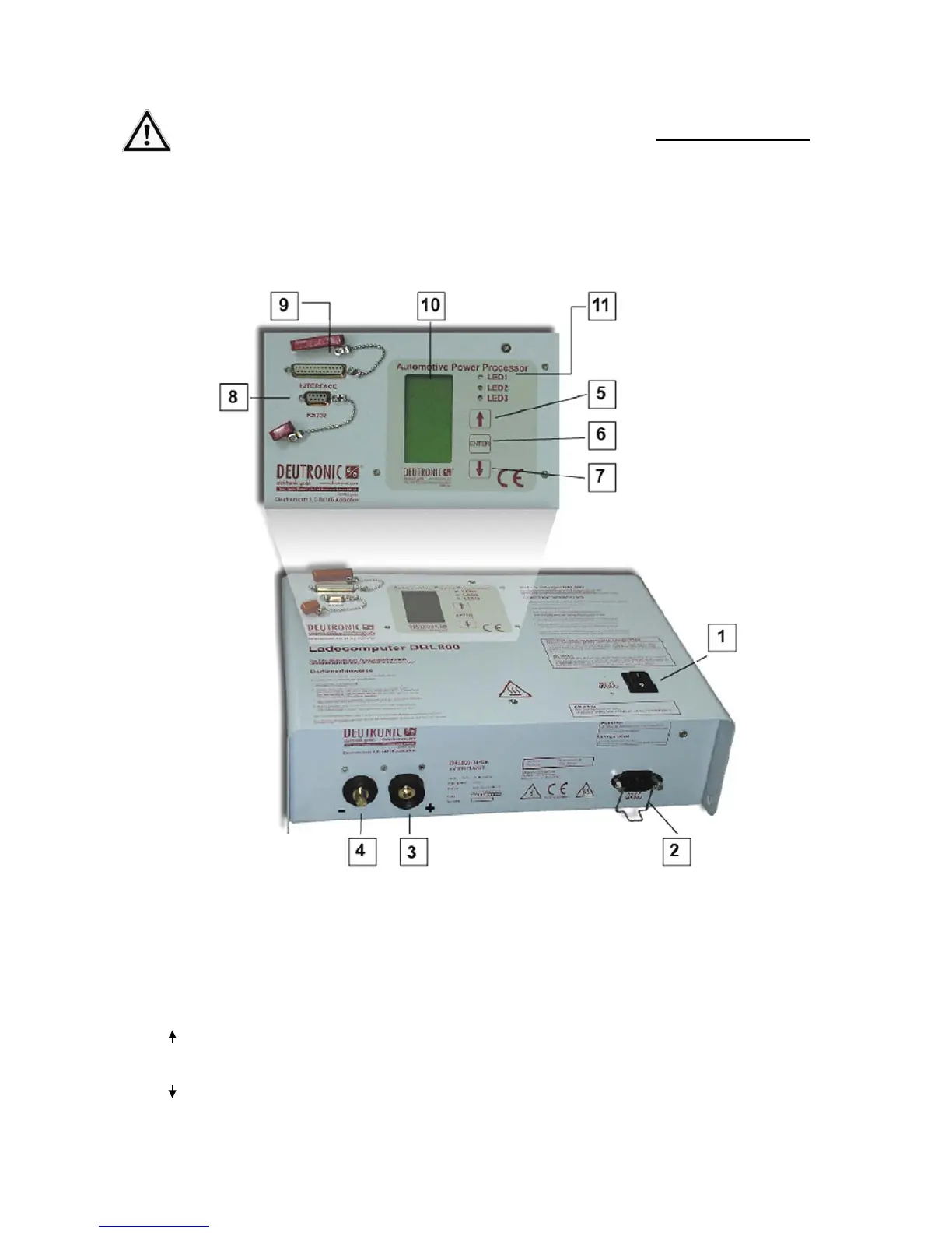
3) Connections and Control Elements
Example for a DBL (BM-housing) with MPC4-control board and 1-phase supply:
[1]
Power switch ON/OFF
[8]
Communication interface (9-pole)
[2]
Connection for power cord with
mains connector (AC IN)
[9]
Signal interface (25-pole)
[3] "+" Plug for POSITIVE (RED) charger cable
(red clamp)
[10]
User menu (LC-Display)
[4]
"
-" Plug for NEGATIVE (BLACK) charger
cable (black clamp), ground
[11]
LED1-3: Signaling operation state, see chapter
8) Annex – Indication / LED and Signal Lamp
[5] UP - Button (select parameter)
[6] ENTER - Button (edit / enter parameter)
[7] DOWN - Button (select parameter)