Page 7SB-2-586-E
INSTALLATION
SETTING
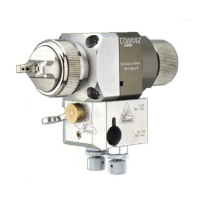
1. The ATOM ‘A’ air valve controls the atomizing air
pressure FAN ‘F’ valve reduces the spray pattern
size. To increase the pressure turn clockwise, to
reduce turn counter-clockwise.
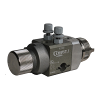
2. Fluid flow can be adjusted with the rear ratchet
knob, fluid flow is increased when you turn the
knob counter-clockwise.
3. For the arrangement of the parts, refer to the
exploded view on page 5.
STARTING UP
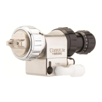
1. Turn the needle adjusting knob (25) clockwise
until the needle is fully closed.
2. Turn the FAN ‘F’ and ATOM ‘A’ air valves (13)
counter-clockwise to be full open.
3. Use the air cap chart above to set the air pressure
at the air regulator to achieve recommended
pressures above.
4. Turn the adjusting knob (25) counter clockwise to
obtain the desired fluid flow.
5. Test spray. If the finish is too dry or fine, reduce
the airflow by reducing the air inlet pressure or
by screwing the valve ATOM ‘A’ (13) in clockwise,
or increase the fluid flow using ratchet knob,
rotating counter clockwise.
Important: To ensure that this equipment reaches you in first class condition,
protective coatings have been used. Flush the equipment through with appropriate
solvent before use. Mount the spray gun using mounting stem ref.28 and secure it
with nut ref.29.
Important: The Spray gun must be grounded to dissipate any electrostatic charges
which may be created by fluid or air flows. This can be achieved through the Spray
gun mounting, or conductive air/fluid hoses. Electrical bond from the spray gun to
earth should be checked with an ohmmeter. A resistance of less than 10
6
Ohms is
recommended.
Use separate filtered regulated air supplies for
atomizing and cylinder air. Connect the cylinder air
‘CYL AIR’ on top of the body via a control valve.
For fast cylinder operation the control valve should
be fitted as close to the gun as possible or an addi-
tional quick exhaust valve installed in the line.
Attach atomizing air hose to the inlet threaded
hole ‘FAN & ATOM AIR’ under the gun body.
Connect material hose(s) ‘P’ to the spray head. If
material re-circulation is required, remove plugs
(30) & (32). Fit standard connector (¼” BSPP) to
the spray head.
Recommended hose size up to 34 ft. (10 m) long:
Atomization Air = 0.315 in. (8 mm)
Cylinder Air = 0.236 in. (6 mm)
Material = 0.315 in. (8 mm)
AIR AND FLUID HOSES
See pages 11, 12, 13 and 14 for installation details.