SB-2-253-I Page 3
Ref. Replacement Individual
No. Part No. Description Parts Required
1 See Chart 2 Air Cap/Retaining Ring ............................................ 1
2 MBC-368 Air Cap Retaining Ring ............................................ 1
3 JGA-156-K10 Spring Clip . .............................................................. 1
4 See Chart 3 Fluid Tip and Needle . ............................................. 1
* 5 JGD-14-K10 Gasket Kit (Kit of 10) . .............................................. 1
(Polyethylene)
6 JGD-402-1 Baffle and Gasket Kit . ............................................. 1
7 --- Fluid Inlet Gasket (PTFE) ......................................... 1
8 --- Lock Nut .................................................................... 1
9 --- Fluid Inlet Nipple . .................................................... 1
10 JGA-4042 Fluid Inlet and Nut Kit .............................................. 1
•*11 JGS-72-K10 Gasket Kit (Kit of 10) (PTFE ) ................................... 2
*12 --- Spring ....................................................................... 1
*13 --- Air Valve ................................................................... 1
•*14 --- U Cup Seal ................................................................ 1
*15 --- Washer ...................................................................... 1
*16 --- Snap Ring . ............................................................... 1
17 JGS-449-1 Air Valve Assembly ................................................. 1
•*18 JGV-463-K3 Packing Kit (Kit of 3) . .............................................. 1
19 34411-122-K10 Packing Nut Kit (Kit of 10) . ..................................... 1
*20 --- Screw ........................................................................ 1
21 JGS-478 Stud and Screw Kit (Kit . ......................................... 1
(includes 3 studs and 5 screws)
22 JGS-477-1 Trigger, Stud and Screw Kit
(Kit includes 1 each) .............................................. 1
23 JGA-132 Plug ........................................................................... 1
24 P-MB-51 Air Inlet Connector 1/4" NPS(M) . ........................... 1
25 JGA-497-1 Spreader Adjustment Assembly ............................ 1
*26 --- Retaining Ring .......................................................... 1
•*27 --- O-Ring (Viton) .......................................................... 1
28 JGS-16 Adjusting Screw ....................................................... 1
*29 --- Spring Pad (Included with # 30 and 32) . .............. 1
*30 MBD-19-K10 Spring Kit (Kit of 10) . .............................................. 1
31 --- Bushing ..................................................................... 1
32 JGA-4041 Bushing, Spring, Pad and Knob Kit ........................ 1
33 --- Gun Body .................................................................. 1
* A quantity of necessary parts is included in repair kit ■ KK-4987-2 for complete gun
repair and should be kept on hand for service convenience.
• A quantity of necessary parts is included in Minor Repair Kit KK-5034 for gun repair.
Suffixes - K10 designates kits of multiple parts. (Example) JGD-14-K10 is a kit of 10
gaskets.
■Government NSN No. 4940-01-046-9919 = KK-4987-2
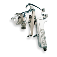
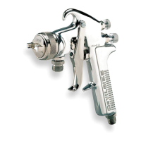
PARTS LIST
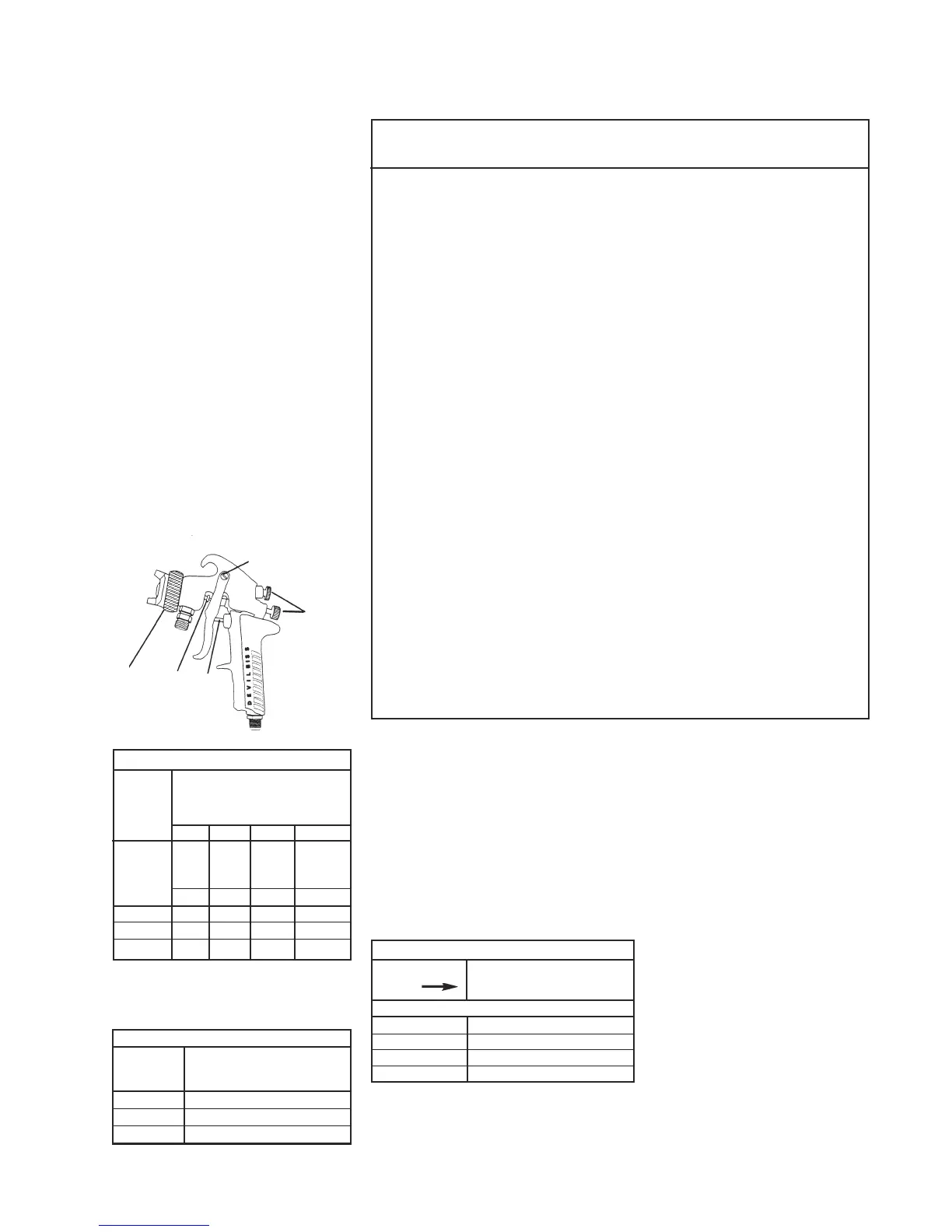
SPRAY GUN LUBRICATION
Daily, apply a drop of *SSL-10 gun lube at
trigger bearing stud (21) and the stem of
the air valve (13) where it enters the air
valve assembly (17). The shank of the fluid
needle (4) where it enters the packing nut
(19) should also be oiled. The fluid needle
packing (18) should be lubricated periodi-
cally. Make sure the baffle (6) and retaining
ring (2) threads are clean and free of foreign
matter. Before assembling retaining ring to
baffle, clean the threads thoroughly, then
add two drops of SSL-10 spray gun lube to
threads. The fluid needle spring (30) and air
valve spring (12) should be coated with a
very light grease, making sure that any
excess grease will not clog the air pas-
sages. For best results, lubricate the points
indicated daily with SSL-10 spray gun lube.
A. Trigger Points
B. Packing
C. Adjusting Valves
D. Baffle Threads
E. Air Valve Cartridge
* Not for air tools or high RPM equipment.
"Material Safety Data Sheet" available from
DeVilbiss upon request.
A
C
E
B
D
STAINLESS STEEL TIPS AND NEEDLES
AV-2115-EX JGA-4040-EX (matched set)
AV-2115-FF JGA-4040-FF (lapped set)
AV-2115-FW JGA-4040-FW (matched set)
AV-2115-FX JGA-4040-FX (lapped set)
AV-1 copper gasket is included with all fluid
tip and needle sets, but is not required and
should not be used on this spray gun.
CHART 3
FLUID TIPS AND NEEDLES
If this is No. Ref. No. 4
on Tip Tip & Needle Sets
Order
EX FW FF FX
Tip
Orifice
in./ .070 .063 .055 .042
mm 1.8 1.6 1.4 1.1
80 S S
777 P
9000 S S P
S = Suction Feed Combination
P = Pressure Feed Combination
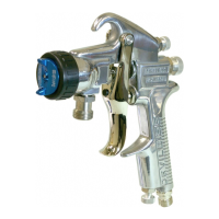
NOZZLE COMBINATIONS
Air Cap
Sizes
Order
From
Chart 2
Fluid Tip and Needle Sizes
Order From Chart 3
CHART 1
No. on Ref. No. (1)
Cap Air Cap
Order With Ring
80 MB-4039-80
777 AV-440-777
9000 AV-440-9000
AIR CAPS
CHART 2
♦
 Loading...