Page 2 SB-2-240-C
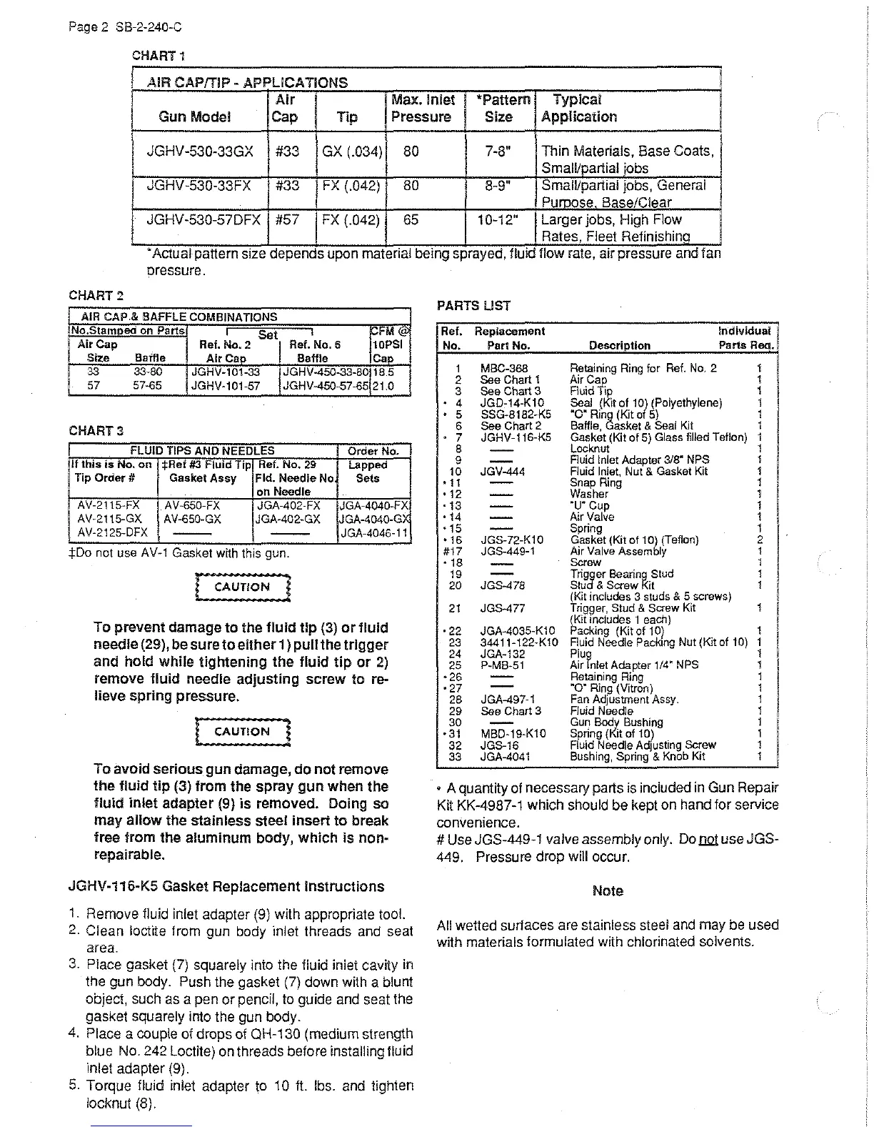
CHART1
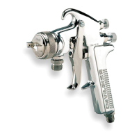
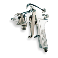
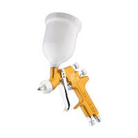
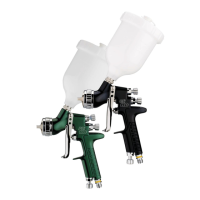
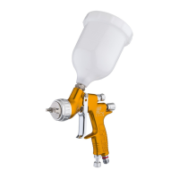
1 AIR CAP/TIP APPLICATIONS
-
I
Air
I
Max. Inlet
I
*Pattern I Typical
Gun Model Cap Tip
Pressure
Size
Application
JGHV -530-33GX #33
GX
(.034) 80 7-8" Thin Materials, Base Coats, I
Small/partial
jobs
JGHV -530-33FX
I #33
I
FX
(.042)
80
I
8-9" SmaiVpartial jobs, General
Puroose Base/Clear
JGHV-530-57DFX #57
I
FX
(.042)
65
1 0-12"
Larger jobs, High Flow
Rates. Fleet Refinishino
.
Actual pattern
SIZe
depends upon matenal bemg sprayed,
flUid
flow rate,
a1r
pressure
and
fan
oressure.
CHART2
AIR CAP.& BAFFLE COMBINATIONS
No.Stamped
on Parts
I
Set
I
Air Cap
Ref.
No.2
I
Ref.
No.6
c;FM_';9'
10PSI
Size Baffle
Air
Cap Baffle Cap
33
33-80
JGHV-t01-33
I :GHV-450-33-80
18.5
57 57-65
JGHV-101-57 JGHV-450-57-65
21.0
CHART3
I FLUID TIPS AND NEEDLES
If this
is
No.
on
*Ret
#3
Fluid
Tip
Ref. No. 29
Tip
Order#
Gasket
Assy
Fld. Needle No
on
Needle
AV-2115-FX AV-650-FX JGA-402-FX
AV-2115-GX
AV-650-GX
JGA-402-GX
AV-2125-DFX
--
--
:j:Do
not
use
AV-1
Gasket
w1th
this
gun.
!
CAUTION
J
Order
No
Lapped
Sets
JGA-4040-FX
JGA-4040-GX
JGA-4046-t1
To prevent damage
to
the
fluid
tip
(3)
or
fluid
needle (29), be
sure
to
either
1)
pull
the
trigger
and
hold
while
tightening
the
fluid
lip
or
2)
remove
fluid
needle
adjusting
screw
to
re-
lieve
spring
pressure.
l
CAUTION
]
To avoid
serious
gun
damage,
do
not
remove
the
fluid
tip
(3) from the
spray
gun
when
the
fluid
inlet
adapter
(9)
is
removed. Doing
so
may
allow
the
stainless
steel
insert
to
break
tree
from
the
aluminum
body,
which
is
non-
repairable.
JGHV-116-KS Gasket Replacement
Instructions
1.
Remove fluid inlet adapter
(9)
with appropriate tool.
2. Clean loctite from gun body inlet threads and seat
area.
3.
Place gasket
(7)
squarely into the fluid inlet cavity in
the gun body. Push the gasket
(7)
down with a blunt
object, such
as
a pen or pencil,
to
guide and seat the
gasket squarely into the gun body.
4.
Place a couple of drops of QH-130 (medium strength
blue No. 242 Loctite)
on
threads before installing fluid
inlet adapter (9).
5.
Torque fluid inlet adapter to 10 II. lbs.
and
tighten
locknut (8).
PARTS UST
Ref.
Replacement
Individual
No. Part No. Descriotion
Parts ReQ.
t
MBC-368
Retaining
Ring
for
Ref.
No.
2 t
2
See Chart 1
Air
c¥;
1
3 See
Chart3
Fluid ip
1
4
JGD-14-K10
Seal (Kit of 10( (Polyethylene)
1
5
SSG-8182-K5
·o· Ring (l<it o 5)
1
6
See Chart 2 Baffle, asket & Seal Kit
1
7
JGHV-t16-K5 Gasket (Kit
of
5) Glass filled Teflon) 1
B
-
Locknut
1
9
-
Fluid Inlet Adapter 3/8" NPS
1
10 JGV-444
Fluid Inlet, Nut & Gasket
Kit
1
•1t
-
Snap Ring 1
•12
-
Washer
1
·13
-
·u·
Cup 1
•14
-
Air
Valve
t
•15
-
Spring
1
•t6
JGS-72-K10 Gasket (Kit of
tO~
(Teflon)
2
#t7
JGS-449-1
Air
Valve
Assem
ly
1
•18
-
Screw
1
19
-
T
rig3er
BearinR-
Stud
1
I
20 JGS-478
Stu
& Screw
it
1
(Kit
includes
3
studs
& 5
screws}
21
JGS-477 Trigger, Stud & Screw Kit
1
I
~Kit
mcludes
1
each)
• 22
JGA-4035-KtO acking (Kit of 10) 1
I
23
344tt-122-K10
Fluid Needle Packing Nut (Kit of
tO)
t
24 JGA-132
Plu~
t
I
25
P-MB-St
Air nlet Adapter 1/4" NPS 1
I
•26
-
Retaining
Ring
1
• 27
-
·o·
Ring
(Vitron)
1
28
JGA-497-1
Fan
Adjustment
Assy.
1
I
29
See
Chart 3 Fluid Needle
t
I
30
-
Gun
Bod~
Bushing
t
·31
MBD-19-K10 Spring ( it of 10)
t
32
JGS-16
Fluid
Needle
Adjusting
Screw
1
33
JGA-4041
Bushing,
Spring
&
Knob
Kit
1
• A quantny of necessary parts
is
included
in
Gun Repair
Ktt
KK-4987-1 which should be kept on hand for service
convenience.
# Use JGS-449-1 valve assembly only.
Do
LlQt
use JGS-
449. Pressure drop will occur.
Note
All
wetted suriaces are stainless steel
and
may
be
used
with materials
formulated with chlorinated solvents.
 Loading...