English
12
1. Assembly instructions
1.1 Tools required
• Phillips screwdriver PH1, PH2
• 2.5 mm slotted screwdriver
• 5.5 mm socket wrench
• Soldering equipment
• Electronic edge cutter
• Allen key, size 4
• 14 mm combination wrench
• Multimeter with measuring ranges: 0 - 2 V DC, 0 - 20 V DC, 0 -
200 V DC, 0 - 300 V AC
1.2 Removing housing
• Loosen the housing fixing screws which are underneath the
device. (Fig. 1)
• Carefully lift housing upwards.
• Loosen plug from the push button board.
• Remove coaxial cable from securing clip.
• Place cover next to the device.
1.3 Fitting housing
• Attach the cable to the transformer with the securing clip.
• Expose housing and connect plug for push buttons to the
board.
• Close housing, screw to the base plate.
1.4 Fault finding
• Remove housing cover (see point 1.2)
• Connect push button box to the board.
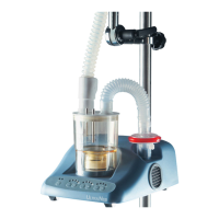
• Fill chamber with distilled water up to the mark and fit cover.
• Fit nebuliser chamber.
• Switch on device.
• Locate fault using the fault-finding table.
• After identifying fault, change the defective component.
• Adjust the device following the setting instructions.
• Remove push button box and housing cover.
• Fit housing cover (see point 1.3)
• Check electrical safety according to VDE 0751 or IEC601-1
• Trial run
1.5 Changing PC board
1.5.1 Removing PC board
• Remove cover (see point 1.2)
• Loosen plug connection (J3)
• Remove M3 nuts
• Remove cable ties from transformer.
• Lift board and unsolder connecting cable for fan and heat
tube (J1, J5, J13) and for the transformer (J8, J9, J10).
• Remove board.
1.5.2 Fitting PC board
• Solder transformer connections to board
white = J10
orange = J8
red = J9
• Solder patient fan into J5 (see Fig. 2)
• Ensure polarity is correct!
• Solder device fan into J13 (see Fig. 2)
• Ensure polarity is correct!
• Solder heat tube connector (J1)
• Locate board onto the fixing bolts and attach using M3 nuts.
• Connect plug connections to the board (J3).
• Connect push button box to the board.
• Fill chamber with distilled water up to the mark and fit cover.
• Fit nebuliser chamber.
• Switch on device.
• Adjust the device following the setting instructions.
• Remove push button box and housing cover.
• Fit housing cover (see point 1.3)
• Check electrical safety according to VDE 0751 or IEC601-1
• Trial run