Initial use 26
devolo Giga Bridge
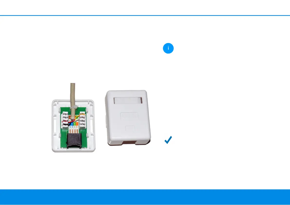
lation displacement terminal has to be used to con-
nect the existing telephone wiring to the G.hn
phone jack of the devolo Giga Bridge. The tele-
phone cable is removed from the demarcation
point and then split and contacted by means of
connection technology involving wire stripping
and soldering or screwing down. A standard net-
work interface is created as a result. Then a classic
network cable (Cat 5e or higher) can be used to es-
tablish a connection to the devolo Giga Bridge
(phone).
Note the correct pin assignment:
b Pin 4/5 for SISO
b Pin 4/5 and 3/6 for MIMO
Incorrect pin assignment results in wires
from different wire pairs being used. This
can impair the transmission. The wiring in
pairs is correct.
1 Plug one adapter of the devolo Giga Bridge
into an available power socket next to the NT/
ONT.
2 Connect the adapter of the devolo Giga Bridge
using the provided network cable with the NT/
ONT.
3 Connect the adapter of the devolo Giga Bridge
using the telephone line (G.hn phone line
socket, phone) to a connection already in the
wall.
The connection between the NT/ONT and
router over the telephone line is
completed.
Fig. 5: Using LSA, the telephone cable becomes a full-
fledged network interface. The devolo Giga Bridge
can be connected via the network cable (phone) to the
ONT