6
ENGLISH
Using an Extension Cable
An extension cord should not be used unless absolutely
necessary. Use an approved extension cable suitable for
the power input of your charger (see Technical Data). The
minimum conductor size is 1.5 mm
2
; the maximum length
is30m.
When using a cable reel, always unwind the cablecompletely.
Package Contents
The package contains:
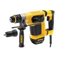
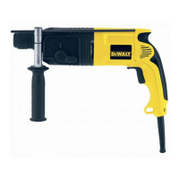
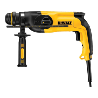
1 Rotary Hammer
1 Side handle
1 Instruction manual
• Check for damage to the tool, parts or accessories which may
have occurred duringtransport.
• Take the time to thoroughly read and understand this manual
prior tooperation.
Markings on Tool
The following pictograms are shown on the tool:
Read instruction manual beforeuse.
Wear earprotection.
Wear eyeprotection.
Date Code Position (Fig. A)
The date code
10
, which also includes the year of manufacture,
is printed into thehousing.
Example:
2017 XX XX
Year of Manufacture
Description (Fig. A)
WARNING: Never modify the power tool or any part of it.
Damage or personal injury couldresult.
1
Trigger switch
2
Side handle
3
Front Barrel (Collar)
4
Mode selector dial
5
Mode selector release button
6
Main handle
7
Bit holder
8
Sleeve
Intended Use
Your rotary hammer has been designed for professional rotary
drilling, chiseling and chippingapplications.
DO NOT use under wet conditions or in the presence of
flammable liquids orgases.
Your rotary hammer is a professional powertool.
DO NOT let children come into contact with the tool.
Supervision is required when inexperienced operators use
thistool.
• Young children and the infirm. This appliance is not
intended for use by young children or infirm persons
withoutsupervision.
• This product is not intended for use by persons (including
children) suffering from diminished physical, sensory or
mental abilities; lack of experience, knowledge or skills
unless they are supervised by a person responsible for their
safety. Children should never be left alone with thisproduct.
Active Vibration Control
For best vibration control, hold the tool as described in Proper
HandPosition.
The active vibration control neutralises rebound vibration from
the hammer mechanism. Lowering hand and arm vibration,
it allows more comfortable use for longer periods of time and
extends the life of theunit.
The hammer only needs enough pressure to engage the active
vibraton control. Applying too much pressure will not make
the tool drill or chip faster and active vibration control will
notengage.
ASSEMBLY AND ADJUSTMENTS
WARNING: To reduce the risk of serious personal
injury, turn tool off and disconnect tool from power
source before making any adjustments or removing/
installing attachments or accessories. Be sure the
trigger switch is in the OFF position. An accidental start-up
can causeinjury.
Side Handle (Fig. A–B)
WARNING: To reduce the risk of personal injury, ALWAYS
operate the tool with the side handle properly installed.
Failure to do so may result in the side handle slipping
during tool operation and subsequent loss of control. Hold
tool with both hands to maximizecontrol.
The side handle
2
clamps to the front of the gear case and may
be rotated 360˚ to permit right- or left-hand use.
Mounting the Straight Side Handle (Fig. B)
1. Widen the ring opening of the side handle
2
by rotating it
anti-clockwise.
2. Place the assembly onto the tool by the putting the nose of
the tool through the steel ring
9
and onto the collar
3
past
the bit holder andsleeve.
3. Rotate the side handle assembly to the desired position. For
hammerdrilling horizontally with a heavy drill bit, place the
side handle assembly at an angle of approximately 20° to
the tool for optimumcontrol.
4. Lock the side handle mounting assembly in place by
securely tightening the handle
2
rotating it clockwise so
that the assembly will notrotate.