ENGLISH
25
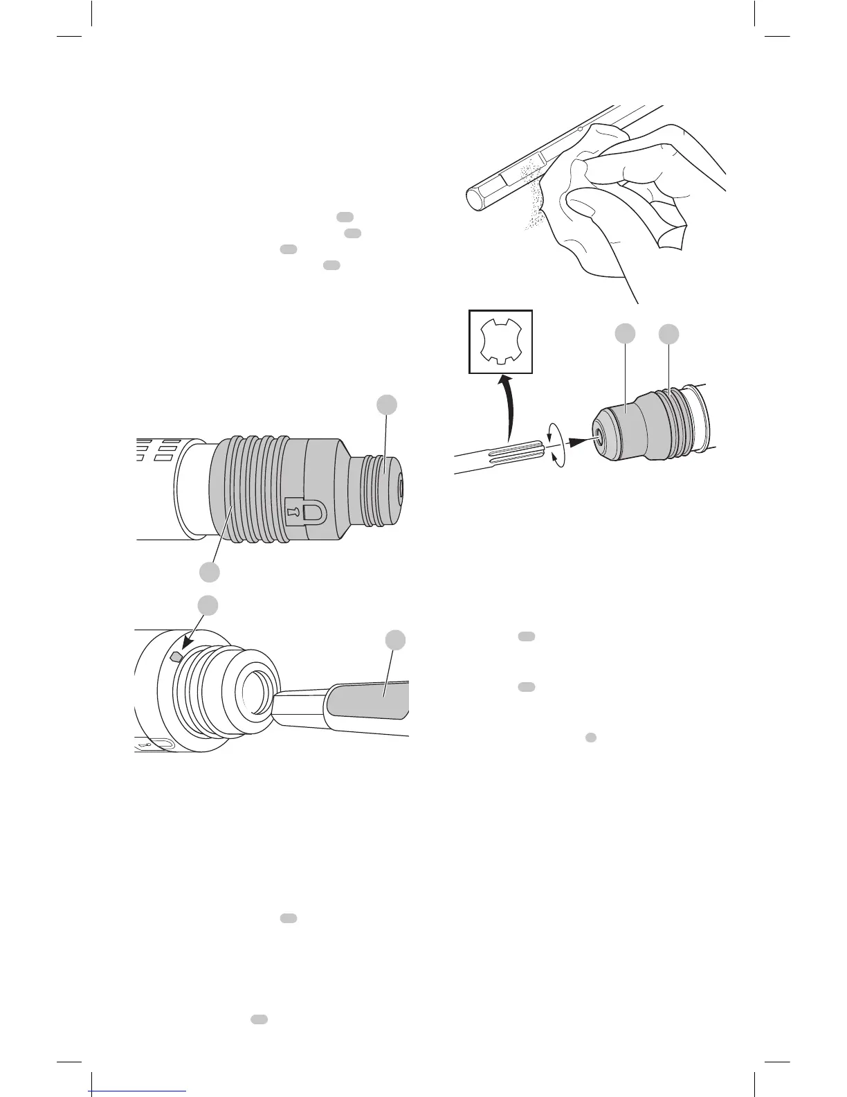
Inserting and Removing Spline Drive
Accessories (Fig. C)
D25851
WARNING: To reduce the risk of serious personal
injury, turn tool off and disconnect tool from
power source before making any adjustments or
removing/installing attachments oraccessories.
1. Insert the bit shank into the tool holder
13
as far as
it will go. The groove on the chisel shank
17
must
be aligned with the symbol
15
on the toolholder. If
inserted correctly, the locking sleeve
16
moves back to
the end position and shows a closed locksymbol.
2. Pull on the bit to be sure that it is properlylocked.
3. If the chisel groove is not aligned with the symbol, or
is not inserted to the complete depth the lock symbol
remainsopen.
4. To remove the bit, pull back the locking sleeve and pull
the bitout.
Fig. C
13
17
15
16
Inserting and Removing SDS Max®
Accessories (Fig. D)
D25501, D25602, D25820, D25831
WARNING: To reduce the risk of serious personal
injury, turn tool off and disconnect tool from
power source before making any adjustments or
removing/installing attachments oraccessories.
1. Pull back the locking sleeve
16
and insert the bit shank.
The bit shank must beclean.
2. Turn the bit slightly until the sleeve snaps back
intoposition.
3. Ensure the bit is properlyengaged.
NOTE: The bit needs to move several centimeters in and
out of the tool holder
13
when properlyengaged.
4. To remove the bit, pull back the locking sleeve and pull
the bitout.
Fig. D
13
16
Complete Torque Control (Fig. E)
D25602
NOTICE: Always turn the tool off before changing
torque control settings or damage to tool mayresult.
The Complete Torque Control (CTC) feature of this tool is
designed to provide additional control with a two-stage
clutchmechanism.
Clutch Setting 1
14
is designed for most hammerdrilling
applications and is designed to easily clutch out when the
drill bit encounters re-bar or other foreignsubstances.
Clutch Setting 2
11
is designed for higher torque
applications such as core-bits and deep hole hammerdrilling
and is designed to clutch out at a higher torquethreshold.
Move the torque control lever
8
to setting 1 or 2 as needed
forapplication.
NOTE: Allow the motor housing to rotate a little while
changingtorque.
Each time the tool is plugged in, it will automatically default
to clutch setting 1, the most sensitivesetting.