ENGLISH
26
14
11
8
7
9
10
Fig. E
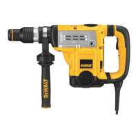
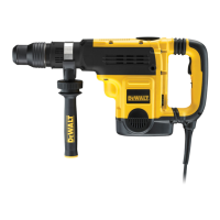
Electronic Speed and Impact Control
(Fig. E)
D25602, D25831, D25851
The electronic speed and impact control allows the
use of smaller drill bits without the risk of bit breakage,
hammerdrilling into light and brittle materials without
shattering and optimal tool control for precisechipping.
To set the control dial, turn the dial
7
to the desired level.
The higher the number, the greater the speed and impact
energy. Dial settings make the tool extremely adaptable for
many different appli cations. The required setting depends
on the bit size and hardness of material beingdrilled.
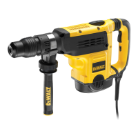
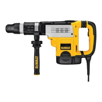
Mode Selector (Fig. A)
CAUTION: Never change the mode while the unit
isrunning.
CAUTION: Do not change to hammerdrill mode with
chisel bit in tool holder. Personal injury and damage
to tool mayresult.
The D25501, D25601, D25602 uses two operating modes.
To select the required operating mode, rotate the mode
selector
6
until the arrow points to the hammerdrilling
or the chipping icon. The D25820, D25831 uses only the
chippingmode.
Hammerdrilling Mode ( )
The tool simultaneously rotates and impacts the
work. This mode is appropriate for all concrete and
masonryoperations.
Chipping Mode ( )
The spindle lock is engaged during chipping mode
so the tool impacts the work without rotating. This
mode is appropriate for light chipping, chiseling and
demolitionapplications.
NOTE: In chipping mode, the hammerdrill can also be used
as a lever to free a jammed drillbit.
Chisel Bit Adjustment ( )
Turn the mode selector to one of the chisel bit adjustment
icons to adjust the chisel to the desired position. There are
18 possible positions to set the angle of the chisel. After
finding the desired position, slightly maneuver the chisel bit
back and forth to ensure the chisel is properlyengaged.
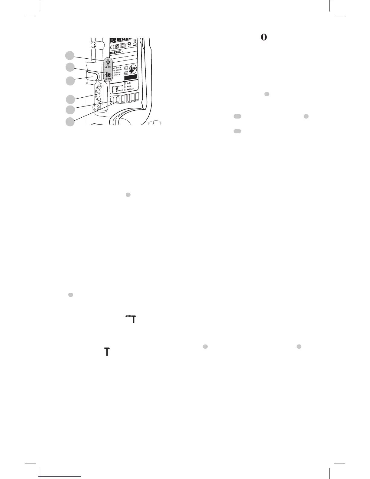
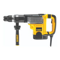
Power Indicator Lights (Fig. A, E)
The yellow brushwear indicator LED
9
lights up when the
carbon brushes are nearly worn out indicating that the tool
needs servicing within the next 8 hours ofuse.
The red indicator LED
10
lights up if the lock-on slider
2
is
used in any mode except the chippingmode.
The red indicator LED
10
flashes if there is a fault with the
tool or if the brushes are completely worn.
OPERATION
WARNING: Always observe the safety instructions
and applicableregulations.
WARNING: To reduce the risk of serious personal
injury, turn unit off and disconnect it from
power source before making any adjustments or
removing/installing attachments or accessories.
An accidental start-up can causeinjury.
WARNING: To reduce the risk of personal injury,
ALWAYS ensure workpiece is anchored or
clamped firmly. If hammerdrilling thin material,
use a wood “back-up” block to prevent damage to
thematerial.
WARNING: To reduce the risk of personal injury,
ALWAYS operate the tool with the side handle
properly installed and securely tightened. Failure
to do so may result in the side handle slipping during
tool operation and subsequent loss of control. Hold
tool with both hands to maximizecontrol.
Proper Hand Position (Fig. F)
WARNING: To reduce the risk of serious personal injury,
ALWAYS use proper hand position as shown.
WARNING: To reduce the risk of serious personal
injury, ALWAYS hold securely in anticipation of a
suddenreaction.
Proper hand position requires one hand on the side
handle
3
, with the other hand on the main handle
4
.
NOTE: Operating temperature of this tool is 19˚ F to
104˚ F (-7˚C to +40˚C). Using the tool outside of this
temperature range will decrease the life of the tool.