20
ENGLISH
Wear earprotection.
Wear eyeprotection.
Carryingpoint.
Keep hands away fromblade.
When using the machine in the thicknessing mode, be aware of the direction
of feed. Never use the machine without shavings collector inposition.
When using the machine in the planing mode, be aware of the direction of
feed. Never use the machine without shavings collector inposition.
Make sure that the cutting blades are properly adjusted. Do not allow
the blades to protrude from the cutterhead by more than 1.1mm.
Date Code Position (Fig. A1)
The date code
36
, which also includes the year of manufacture, is printed into thehousing.
Example:
2019 XX XX
Year of Manufacture
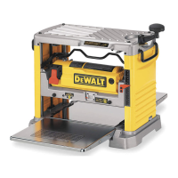
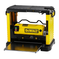
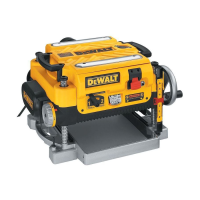
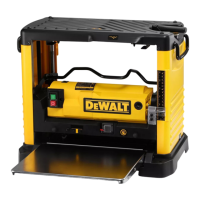
Description (Fig. A1, A2)
WARNING: Never modify the power tool or any part of it. Damage or personal injury
couldresult.
Fig. A1
1
On/off switch
2
Elevating handle
3
Lower table
4
Guard/chip collector
5
Scale lower table
6
Push stick
7
Fence clamp handle
8
Fence
Fig. A2
9
Upper table
10
Planing depth adjustment knob
11
Scale upper table
12
Guard clamp handle
13
Guard
Intended Use
Your DeWALT D27300 Planer and Thicknesser have been designed for professional cutting
of hard and soft wood. It performs planing and thicknessing operations easily, accurately
andsafely.
The cutter block is designed to accept nominal 260 mm blades (DE7333).
WARNING: Do not use the machine for other purposes thanintended.
DO NOT use under wet conditions or in the presence of flammable liquids orgases.
These planers are professional powertools.
DO NOT let children come into contact with the tool. Supervision is required when
inexperienced operators use thistool.
• Young children and the infirm. This appliance is not intended for use by young children
or infirm persons withoutsupervision.
• This product is not intended for use by persons (including children) suffering from
diminished physical, sensory or mental abilities; lack of experience, knowledge or skills
unless they are supervised by a person responsible for their safety. Children should never
be left alone with thisproduct.
ASSEMBLY AND ADJUSTMENTS
WARNING: To reduce the risk of serious personal injury, turn tool off and
disconnect tool from power source before making any adjustments or removing/
installing attachments or accessories. Be sure the trigger switch is in the OFF position.
An accidental start-up can causeinjury.
WARNING: Prior to assembly always unplug thetool.
Unpacking the Machine (Fig. B1)
1. Remove the loose packaging material from thebox.
2. Lift the machine out of thebox.
3. Remove the parts box from the interior of themachine.
4. Remove any remaining packing material from themachine.
Identifying the Hardware Parts (Fig. B2)
We recommend that you unpack and sort all hardwareparts.
14
Wheel bracket
15
Wheel axle
16
M8 coach bolt
17
M8 hex head bolt
18
M8 nut
19
Wing nut
20
D8 toothed washer
21
D8 flat washer
22
D8 flat washer
23
D8 Belleville washer
Mounting the Feet (Fig. C1, C2)
With the feet mounted, the machine is suitable for placement on a workbench. To ensure a
safe operation, the machine has to be fixed to the workbench. Required hardware parts: 4
nuts
18
, 4 toothed washers
20
(Fig. C1).
1. Turn the machine on its side with the thicknessing outfeed frame
24
resting on the floor
(Fig. C2).
WARNING: Take care to avoid that the planing depth adjustment knob
10
hits thefloor.
2. Insert a foot
25
into each of the outer notches
26
located in the bottom of the
machinehousing.
3. Place a toothed washer
20
and a nut
18
onto the threaded end of thefeet.
4. Tighten thenuts.
5. Turn the machine straightup.
6. Fix the machine to theworkbench.
Mounting the Legs (Fig. D1–D3)
With the legs mounted, the machine is suitable for stand-alone placement. Required hardware
parts: 4 coach bolts
16
, 4 wing nuts
19
, 4 flat washers
21
(Fig D1).
1. Turn the machine on its side with the thicknessing outfeed frame
24
resting on the floor
(Fig. D2).
WARNING: Take care to avoid that the planing depth adjustment knob
10
hits thefloor.
2. Insert a leg
27
into each of the top holes
28
located at the edges in the bottom of the
machinehousing.
3. Pass a coach bolt
16
through the holes in the legs and the machinehousing.
4. Place a flat washer
21
and a wing nut
19
onto thebolts.
5. Tighten the wingnuts.
6. Turn the machine on its side with the planing outfeed table
29
resting on the floor
(Fig.D3).
7. Repeat as for the otherfeet.
8. Mount the castor wheels as describedbelow.
Mounting the Castor Wheels (Fig. E1–E3)
Required hardware parts: 2 wheel brackets
14
, 2 wheel axles
15
, 2 bolts
17
, 4 nuts
18
, 2 flat
washers
21
, 2 Belleville washers
23
(Fig. E1).
1. Align each wheel
30
with a bracket
14
and pass a wheel axle
15
through the holes of
each assembly (Fig. E2).
2. Place a flat washer
21
and a nut
18
onto the threaded end of theaxles.
3. Tighten thenuts.
4. Mount a wheel assembly
31
to each of the upper legs
32
using a hex head bolt
17
,
Belleville washer
23
and nut
18
(Fig. E3).
5. Tighten thenuts.
6. Turn the machine straightup.
Mounting the Fence (Fig. F1, F2)
1. Place the fence
8
onto the fence holder
33
(Fig. F1).
2. Pass a coach bolt
16
from underneath through the holder and thefence.
3. Place a flat washer
22
onto the bolt
16
(Fig. F2).
4. Fit the clamp handle
7
onto the bolt
16
.
Mounting the Bridge Guard (Fig. G1, G2)
1. Insert the guard
13
into the guard column
34
(Fig. G1).
2. Locate the guard by fitting the lock screw
35
.
3. Fit the clamp handle
12
to the column
34
(Fig. G2).
Mounting the Guard/Chip Collector
When using the machine in planing mode, the guard/chip collector has to be mounted
underneath the upper table. When using the machine in thicknessing mode, the guard/chip
collector has to be mounted on top of the uppertable.
Thicknessing Mode (Fig. A1, H1, H2)
NOTE: The guard/chip collector is in planingmode.
1. Loosen knobs (
68
,
69
) to remove the guard/chip collector
4
from the upper table
9
.
2. Turn the guard/chip collector over 180˚.
3. Slide the guard/chip collector
4
along the upper table
9
, until the knob
67
aligns with
microswitch
66
.
4. Fix the guard/chip collector by tightening the knobs (
68
,
69
).
Planing Mode (Fig. G1, G2, H3, H4)
1. Turn the elevating handle
2
to totally lower the under table
9
.
2. Loosen knobs (
68
,
69
) to remove the guard/chip collector
4
from the uppertable.
3. Slide guard/chip collector off of uppertable.
4. Turn the guard/chip collector over 180˚.
5. Align the 2 external dust port ribs of the guard/chip collector with the 2 side panelslots.
6. Slide the guard/chip collector forward into the microswitch
66
.
7. Secure the guard/chip collector by tightening the knobs (
68
,
69
).
8. Lower the guard
13
untill it contacts the chip collector and lock it using the guard
clamp
12
).
 Loading...