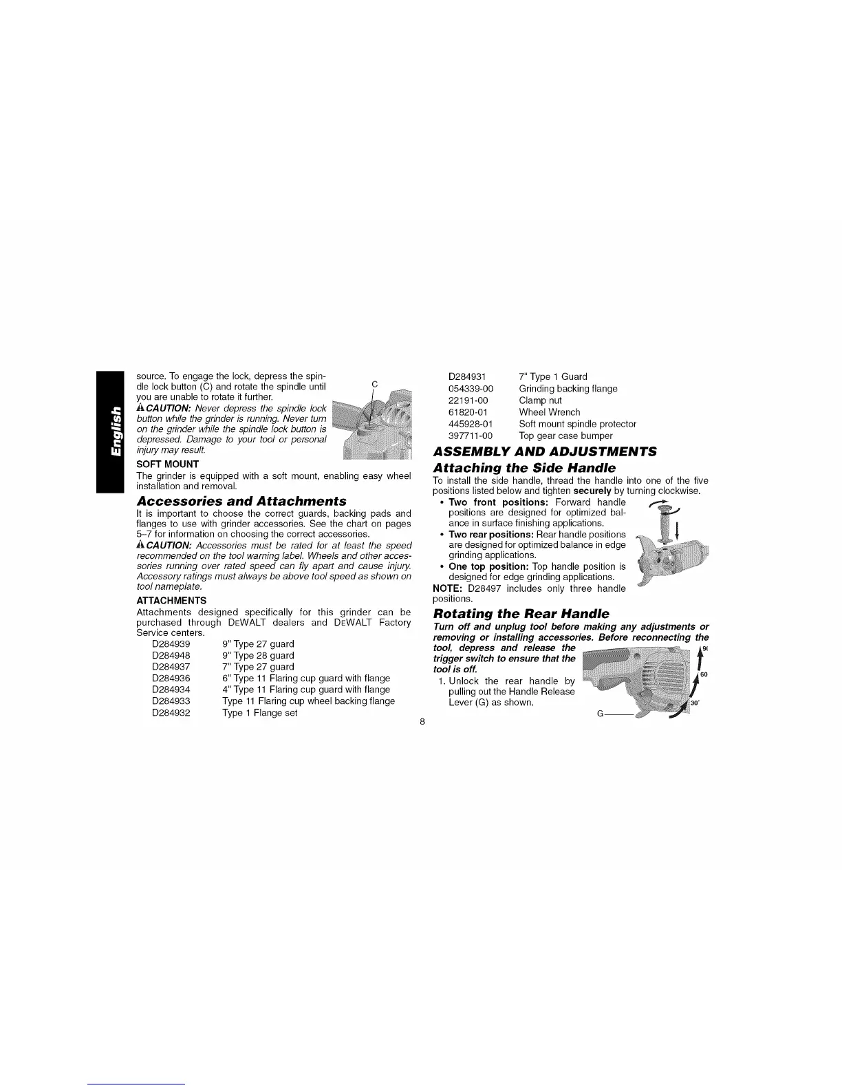
source.Toengagethelock,depressthespin-
dlelockbutton(C)androtatethespindleuntil C
youareunabletorotateitfurther.
ACAUTION:Never depress the spindle lock
button while the grinder b running. Never turn
on the grinder while the spindle lock button is
depressed. Damage to your tool or personal
injury may result.
SOFT MOUNT
The grinder is equipped with a soft mount, enabling easy wheel
installation and removal.
Accessories and Attachments
It is important to choose the correct guards, backing pads and
flanges to use with grinder accessories. See the chart on pages
5-7 for information on choosing the correct accessories.
ACAUTION: Accessories must be rated for at least the speed
recommended on the tool warning label Wheels and other acces-
sories running over rated speed can fly apart and cause injury.
Accessory ratings must always be above tool speed as shown on
tool nameplate.
ATTACHMENTS
Attachments designed specifically for this grinder can be
purchased through
Service centers.
D284939
D284948
D284937
D284936
D284934
D284933
D284932
DEWALT dealers and DEWALT Factory
9" Type 27 guard
9" Type 28 guard
7" Type 27 guard
6" Type 11 Flaring cup guard with flange
4" Type 11 Flaring cup guard with flange
Type 11 Flaring cup wheel backing flange
Type 1 Flange set
D284931
054339-00
22191-00
61820-01
445928-01
397711-00
7" Type 1 Guard
Grinding backing flange
Clamp nut
Wheel Wrench
Soft mount spindle protector
Top gear case bumper
ASSEMBLY AND ADJUSTMENTS
Attaching the Side Handle
To install the side handle, thread the handle into one of the five
positions listed below and tighten securely by turning clockwise.
• Two front positions: Forward handle
positions are designed for optimized bal-
ance in surface finishing applications.
• Two rear positions: Rear handle positions
are designed for optimized balance in edge
grinding applications.
• One top position: Top handle position is
designed for edge grinding applications.
NOTE: D28497 includes only three handle
positions.
Rotating the Rear Handle
Turn off and unplug tool before making any adjustments or
removing or installing accessories. Before reconnecting the
tool, depress and release the Ag_
trigger switch to ensure that the
f
tool is off. 60
1. Unlock the rear handle by
pulling out the Handle Release
Lever (G) as shown.