ENGLISH
31
Worklight (Fig. A)
There is a worklight
3
located under the torque adjustment
collar
4
. The worklight will be activated when the trigger
switch is squeezed.
NOTE: The worklight is for lighting the immediate work
surface and is not intended to be used as a flashlight.
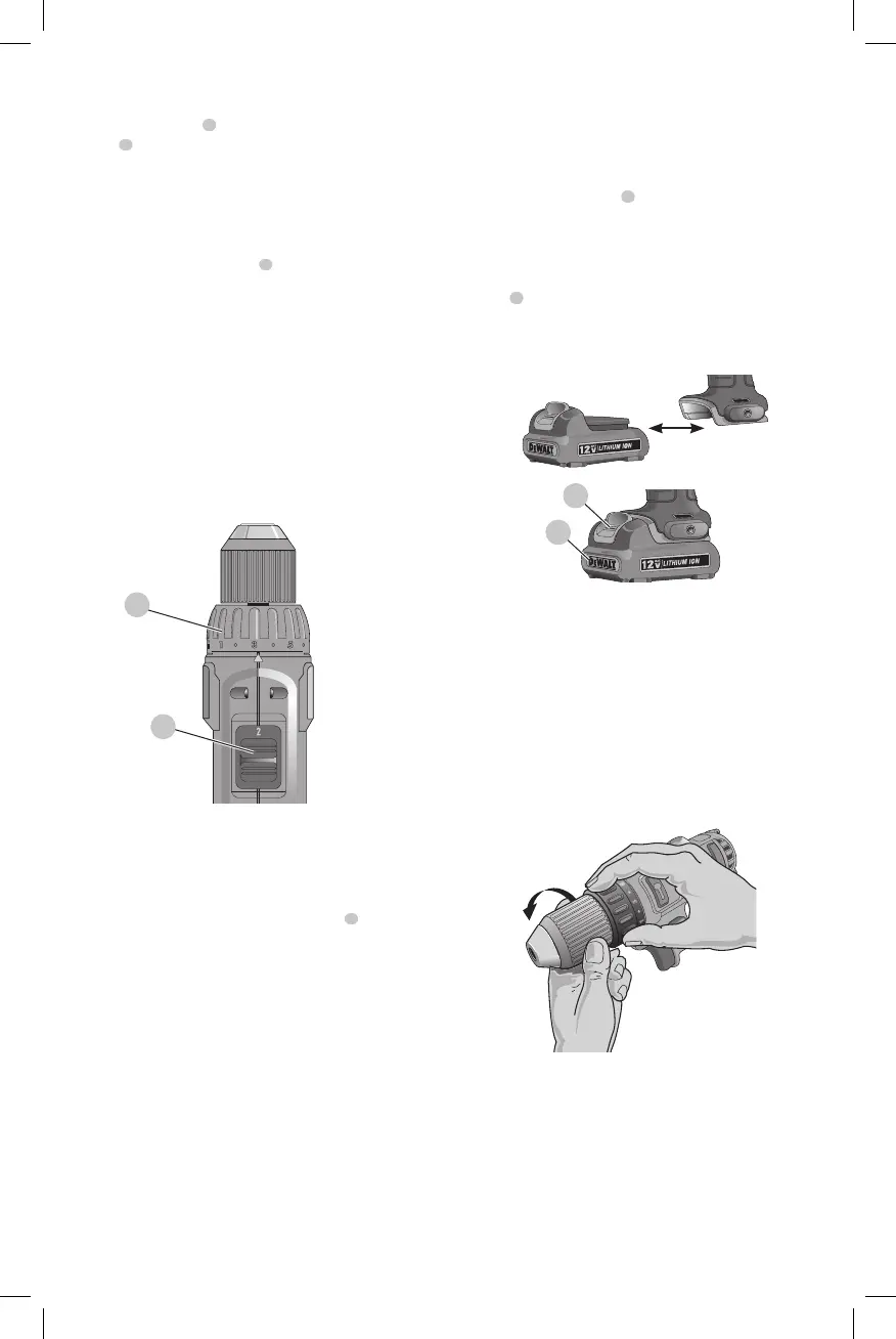
Torque Adjustment Collar (Fig. D)
The torque adjustment collar
4
is clearlymarked with
numbers and a drill bit symbol.The collar should be rotated
until the desired setting is located at the top of the tool.
Locators are provided in the collar to eliminate the guess
work when selecting fastening torque. The higher the
number on the collar, the higher the torque and the larger
the fastener which can be driven. To lock the clutch for
drilling operations, move to the drill bit position.
NOTE: When using the drill/driver for drilling holes, be sure
that the torque adjusting collar is set so the figure of the drill
is aligned with the center line on the top of the tool. Failure
to do this will allow the clutch to slip while attempting
todrill.
Fig. D
4
5
Dual Range Gearing (Fig. D)
The dual range feature of your driver/drill allows you to shift
gears for greater versatility.
To select the low speed, high torque setting, turn the tool
off and permit to stop. Slide the gear shifter
5
forward
(towards the chuck). To select the high speed, low torque
setting, turn the tool off and permit to stop. Slide the gear
shifter back (away from chuck).
NOTE: Do not change gears when the tool is running. If you
are having trouble changing gears, make sure that the dual
range gear shifter is either completely pushed forward or
completely pushed back.
OPERATION
WARNING: Always observe the safety instructions
and applicable regulations.
WARNING: To reduce the risk of serious personal
injury, turn unit off and remove the battery pack
before making any adjustments or removing/
installing attachments or accessories. An
accidental start-up can causeinjury.
Installing and Removing the Battery Pack
(Fig. E)
NOTE: For best results, make sure your battery pack is
fullycharged.
To install the battery pack
8
into the tool handle, align the
battery pack with the rails inside the tool’s handle and slide
it into the handle until the battery pack is firmly seated in
the tool and ensure that it does notdisengage.
To remove the battery pack from the tool, press the release
button
7
and firmly pull the battery pack out of the tool
handle. Insert it into the charger as described in the charger
section of thismanual.
Fig. E
7
8
Keyless Single Sleeve Chuck (Fig. F)
Your tool features a keyless chuck with one rotating sleeve
for one-handed operation of the chuck. To insert a drill bit or
other accessory, follow these steps.
1. Lock the trigger in the OFF position as previously
described.
2. Grasp the black sleeve of the chuck with one hand and
use the other hand to secure the tool. Rotate the sleeve
counterclockwise far enough to accept the desired
accessory.
Fig. F
3. Insert the accessory about
3/4" (19 mm) into the chuck and tighten securely by
rotating the chuck sleeve clockwise with one hand while
holding the tool with the other. Your tool is equipped
with an automatic spindle lock mechanism. This allows
you to open and close the chuck with one hand.
To release the accessory, repeat step 2 above.
 Loading...