ENGLISH
4
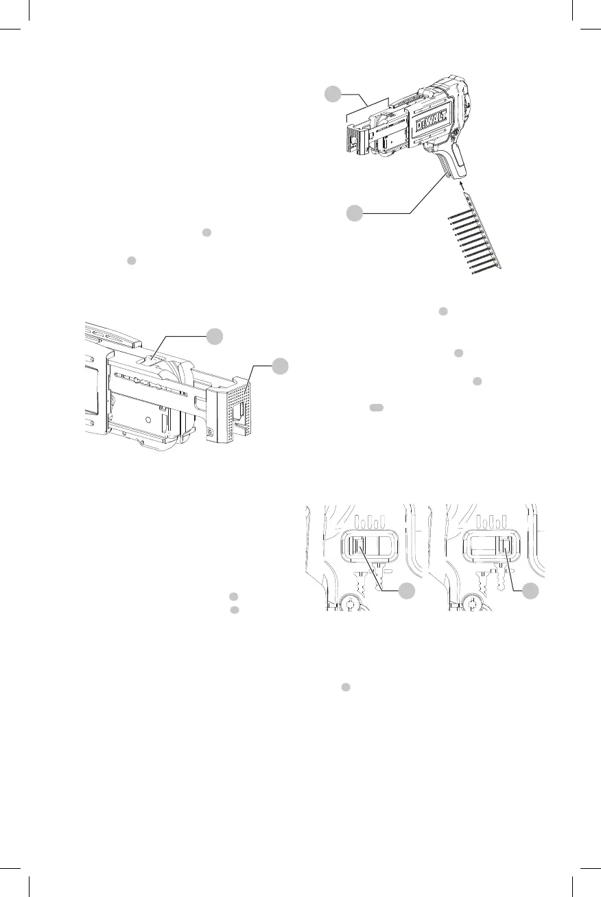
Inserting Collated Screw Strips (Fig.A, F)
NOTICE: Use only screw strips that are suitable to
this magazine. Only insert screw strips when the
screwdriver power is off and the trigger islocked.
Proper use of collated strips will reduce the risk of
injury, reduce jams and prevents screws from damaging
workpiece. For best performance use new, undamaged
strips free ofdebris.
1. Take a collated strip, holding the plastic portion, and
feed from the bottom of the screw guide
1
and into
the bottom of the advancing mechanism
5
.
2. Continue feeding the strip until the first screw is 1 slot
below the driverbit.
NOTE: Do not pull screw strip out from bottom.
continue to pull screw strip out through the top
ifneeded.
Driving Screws (Fig.A)
1. Before driving screws, ensure screwgun drive direction
is switched to forwardposition.
2. With the magazine installed on the screwgun, position
shoe
7
on workpiece in location where screw is to
bedriven.
3. Switch the screwgun on by holding the trigger in the on
position. Continue to hold trigger or engage the trigger
lock-on.
4. Apply pressure against workpiece. This will advance
screw into alignment with screwdriverbit.
5. Continue to apply consistent pressure until screw is
driven in completely and screwgun clutchesdisengage.
6. Lift screwgun fromworkpiece.
Fig. G1 Fig. G2
1414
Setting Screw Depth (Fig.A,G1, G2)
Turn fine depth adjustment knob
3
counterclockwise (as
viewed from behind the tool) to reduce the screw drive
depth into the workpiece.
Turn the fine depth adjustment knob
3
clockwise to
increase the screw drive depth into the workpiece.
There is a fine depth adjustment indicator
4
next to the
adjustment wheel which displays the screw depth setting.
When the slider
14
of the gauge is furthest back from the
nose of the tool, as in Fig.G2, the screw driving depth is set
to the deepest possibleposition.
When the slider is closest to the nose of the tool, as in
Fig.G1, the screw driving depth is set to proudest (most
raised)position.
Fig. E
7
2
Fig. F
1
5
Setting Magazine Screw Length (Fig.E)
This magazine is designed for 1"–2" (20–50mm) screw
lengths. Failure to set the correct screw length can cause
screws to not be driven accurately which can result in the
failure to advance to the next screw or screws not being
driven properly. The shoe has marked specific slots for each
of the most common screws, however this attachment can
still drive any size screw between 1"–2" (20–50mm). To
accommodate for less common screws adjust to the next
longestslot.
CAUTION: Do not adjust while a screw strip is in
themagazine.
1. Slide screw length adjustment tab
2
to theleft.
2. Holding the screw length adjustment tab in place,
adjust the shoe
7
to the desiredlength.
3. Release the screw length adjustment tab. Make sure
that the locking pin has fully returned and is in the
correctposition.