ENGLISH
9
TOOL SPECIFICATIONS
Actuation mode Sequential and RapidCycle
Voltage 20V
Height 16.9" (429 mm)
Width 4.1" (104 mm)
Length 14.2" (361 mm)
Weight 8.8 lbs (3.99 kg)
Magazine angle 0˚
Loading capacity Up to 35 staples
Dry fire lock-out 5 staples
STAPLE SPECIFICATIONS
IMPORTANT: Your fencing stapler is ONLY compatable
with
staples.
Staple lengths 1-1/2", 1-3/4" and 2"
(38 mm, 44.4 mm and 50.1 mm)
Shank diameters 4 mm
Staple angle 0˚
Dry Fire Lock Out
Your stapler is equipped with a dry fire lockout which
prevents the tool from actuating when the magazine is
nearly empty. When 5 staples remain in the magazine, the
tool ceases to operate. Refer to LoadingtheTool to reload a
stick of collatedstaples.
ASSEMBLY AND ADJUSTMENTS
WARNING: To reduce the risk of serious personal
injury, turn unit off and remove the battery pack
before making any adjustments or removing/
installing attachments or accessories. An
accidental start-up can causeinjury.
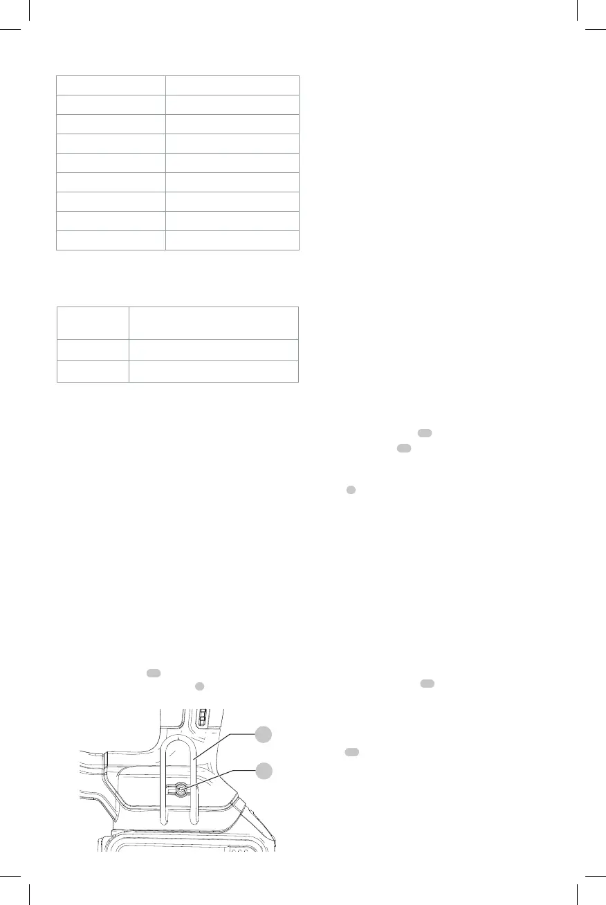
Utility Hook (Fig. D)
If the hook is not desired at all, it can be removed from
thetool.
To Remove Utility Hook
1. Remove battery pack from tool.
2. To switch the tool from right- to left-hand usage simply
remove the screw
15
from the opposite side of the tool
and re attache the utility hook
5
on the other side.
3. Replace battery pack.
Fig. D
5
15
WARNING: Remove staples from magazine before
making any adjustments or servicing this tool. Failure
to do so may result in serious injury.
WARNING: Disconnect battery pack from tool before
making any adjustments, changing accessories,
servicing, or moving the tool. Such preventative
safety measures reduce the risk of starting the
toolaccidentally.
CAUTION: When not in use, place tool on its side on
a stable surface where it will not cause a tripping or
falling hazard. Some tools with large battery packs
will stand upright on the battery pack but may be
easily knocked over.
OPERATION (FIG. A)
WARNING: To reduce the risk of serious personal
injury, turn unit off and remove the battery pack
before making any adjustments or removing/
installing attachments or accessories. An
accidental start-up can causeinjury.
WARNING: Read the section titled Stapler Safety
Warnings at the beginning of this manual. Always
wear eye and ear protection when operating this
tool. Keep the stapler pointed away from yourself and
others. For safe operation, complete the following
procedures and checks before each use of thestapler.
1. Wear proper eye, hearing and respiratoryprotection.
2. Remove battery pack
14
fromtool.
3. Lock the pusher
12
in the back position and remove all
staples from themagazine.
4. Check for smooth and proper operation of contact
trip
7
and pusher assemblies. Do not use tool if either
assembly is not functioning properly. NEVER use a tool
that has the contact trip restrained in the upposition.
5. NEVER use a tool that has damagedparts.
WARNING: To reduce the risk of personal injury,
disconnect battery pack from tool before performing
maintenance, clearing a jammed staple, leaving work
area, moving tool to another location or handing the
tool to anotherperson.
Installing and Removing the Battery Pack
(Fig. E)
NOTE: For best results, make sure your battery pack is
fullycharged.
To install the battery pack
14
into the tool handle, align the
battery pack with the rails inside the tool’s handle and slide
it into the handle until the battery pack is firmly seated in
the tool and ensure that it does notdisengage.
To remove the battery pack from the tool, press the release
button
13
and firmly pull the battery pack out of the tool
handle. Insert it into the charger as described in the charger
section of thismanual.