ENGLISH
11
Power
Setting
Application Typical Staple Length
1
Shorter staple length / minimal
staple drive desired
1-1/2" (38 mm) typical
2
Increased staple drive desired for
medium to large staple lengths
1-3/4"–2"
(44.4 mm–51.1 mm) typical
3 Maximum staple drive desired
1-3/4"–2"
(44.14 mm–51.1 mm) typical
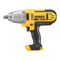
WARNING: Staples must be driven straight into the
material. Do not tilt stapler while driving fasteners.
Refer to Fig.J. Staple retention values improve when
the tool is fired perpendicular to thematerial.
Fig. J
Adjusting Depth (Fig. K)
The depth that the staple is driven can be adjusted using
the tool free depth adjust
6
on the nose of thetool.
WARNING: To reduce risk of serious injury from
accidental actuation when attempting to adjust
depth, ALWAYS:
• Remove battery pack
• Engage trigger lock-off.
• Always point the nose of the stapler away
fromyou.
• Avoid contact with trigger duringadjustments.
1. To drive the staple shallower, rotate the tool free depth
adjust
6
to the left.
2. To drive a staple deeper, rotate the tool free depth
adjust
6
to the right.
Fig. K
6
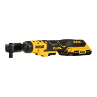
Selecting the Mode (Fig. A)
WARNING: Always wear proper eye [ANSI Z87.1
(CAN/CSA Z94.3)] and ANSI S12.6 (S3.19) hearing
protection when operatingtool.
To select standard sequential mode, slide the tool free mode
select switch
4
to display the single arrow icon.
Fig. H
12
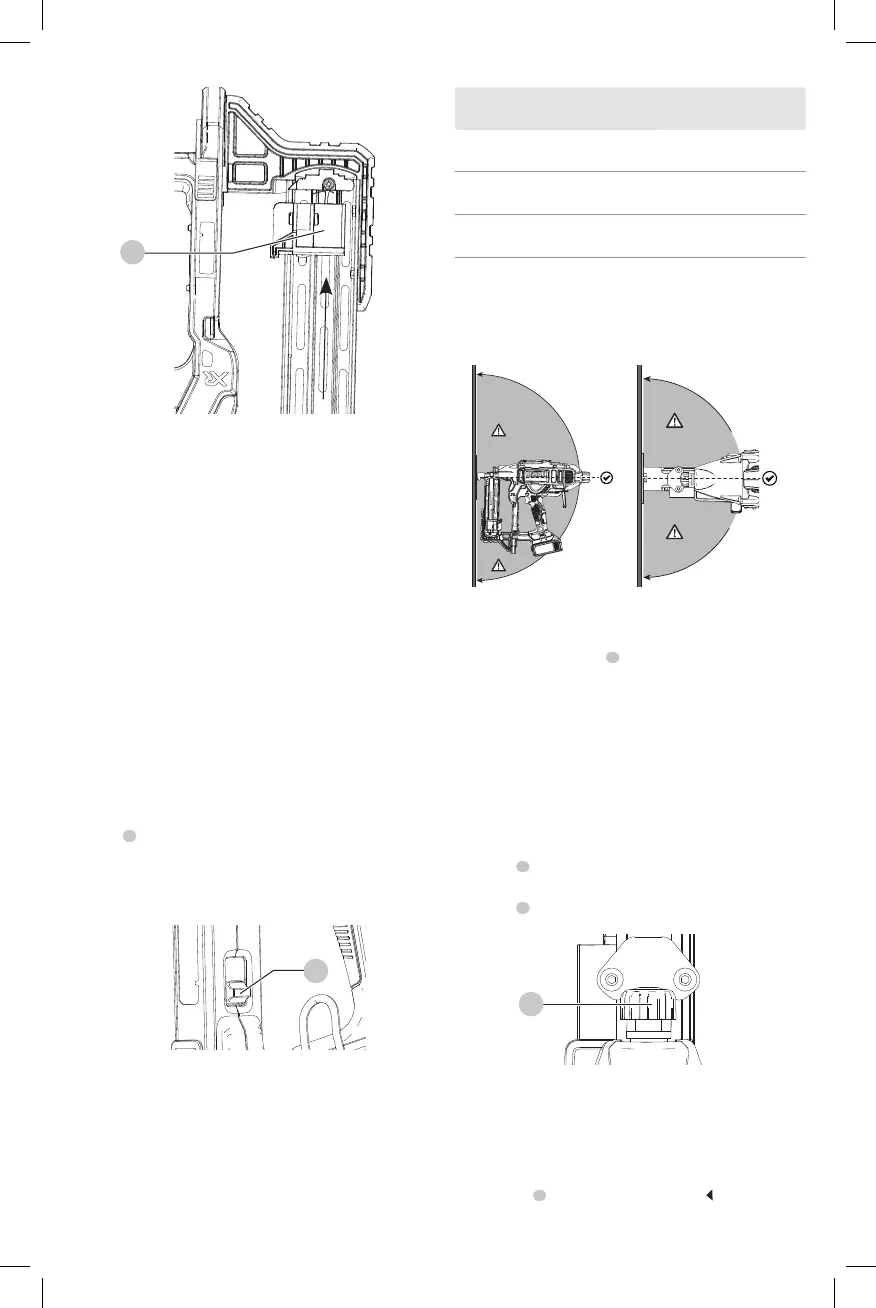
3. Drop staple strips into the loading slot of the magazine,
making sure the staple heads align correctly with
the slot opening. (Refer to Staple Specifications to
determine compatible size.)
4. Keeping fingers clear of the track, close the magazine by
releasing the pusher latch. Carefully allow the latch to
slide forward and engage the staplestrip.
Unloading the Tool
WARNING: The trigger lock-off should always be
locked off whenever any adjustments are made or
when tool is not inuse.
1. Slide the spring-loaded pusher to the base of the
magazine to lock it intoplace.
2. Tip the tool up until the fastener strip slides freely out of
themagazine.
3. With battery removed, check the nosepiece to verify
there are no staplesremaining.
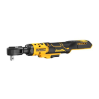
Power Setting Summary (Fig. I, J)
This stapler is equipped with a tool free power select
switch
3
to adjust the tool for differentapplications.
In the event staples are not driving to depth in power
setting1, you may have to switch to power 2 or 3 for
additional drivingpower.
Fig. I
3
NOTICE: Driving staples into soft materials at
high power settings will cause excessive wear to
your tool and may result in earlyfailures.