ENGLISH
14
Fig. P
19
10. Return the driver, guide rods, bumpers and housing
end cap back onto the unit. It is important to try
the alignment of the driver and the flywheel before
screwing the housing end cap back on to the unit. This
can be done by connecting a battery and pushing then
releasing the nose of the unit against a bench or hard
surface. This will start the motorspinning.
NOTE: When the driver and the flywheel are correctly
aligned, you will hear the motor coast back down
from full speed. If the driver and the flywheel are not
correctly aligned, the motor may not start up, may
slow down much faster than normal along with a loud
grinding noise from the unit. If this happens remove
and reseat the driver, making sure the bumpers are
seatedcorrectly.
WARNING: Always test the unit by firing 1-1/2"
(38mm) staples in power setting 1 into scrap material,
to ensure that the tool is working properly. If tool does
not operate properly, contact a recognized
service centerimmediately.
Recommended accessories for use with your tool are
available at extra cost from your local dealer or authorized
service center. If you need assistance in locating any
accessory, please contact
Industrial Tool Co., 701
East Joppa Road, Towson, MD 21286, call 1–800–4-
(1–800–433–9258) or visit our website www.
.com.
Repairs
The charger and battery pack are notserviceable.
WARNING: To assure product SAFETY and
RELIABILITY, repairs, maintenance and adjustment
(including brush inspection and replacement) should
be performed by a
factory service center
or a
authorized service center. Always use
identical replacementparts.
Register Online
Thank you for your purchase. Register your product nowfor:
• WARRANTY SERVICE: Registering your product will
help you obtain more efficient warranty service in case
there is a problem with yourproduct.
• CONFIRMATION OF OWNERSHIP: In case of
an insurance loss, such as fire, flood or theft, your
registration of ownership will serve as your proof
ofpurchase.
DCFS9501 Driver Blade Replacement Kit
(Fig. N–P)
WARNING: For your own safety, read the tool
instruction manual before using any accessory.
Failure to heed these warnings may result in serious
personal injury and damage to the tool and the
accessory. When servicing this tool, use only identical
replacementparts.
NOTICE: All the mechanical parts of the driver
replacment kit are shown for convenience and
verification ofinclusion.
To change a worn driver:
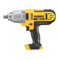
1. Using a T-20 Torx, loosen the four screws
17
on either
side of the unit. Refer to FigureN.
2. Remove the four screws. Refer to FigureN.
3. Remove housing end cap
18
. Refer to FigureN.
Fig. N
18
17
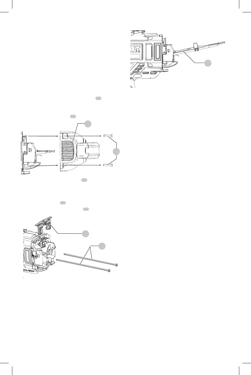
4. Push up on the rear of the driver
19
until you hear a
click, then push the driver forward while holding it in
this position until it passes the upper bumper assembly.
Refer to FigureP.
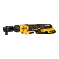
5. Remove guide rods
20
. Refer to FigureO.
6. Remove upper bumper assembly
21
. Refer to FigureO.
Fig. O
20
21
7. Lift the rear of driver until at an angle and pull the driver
out. Refer to FigureP.
8. Replace driver and follow steps in reverse to reassemble
9. Ensure new driver slides smoothly through the gun
before fullreassembly.