11
ENGLISH
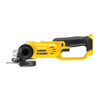
Description (Fig. A)
WARNING: Never modify the power tool or any part of it.
Damage or personal injury couldresult.
1
Variable speed rocker switch
2
Lock-off button
3
Spindle
4
Collet nut
5
Small spanner (13 mm)
6
Large spanner (17 mm)
7
Collet (6.0 mm)
8
Battery
9
Battery release button
10
Grinder body
11
Grinder neck
12
LED Worklight
13
Speed selector switch
14
Date code
Intended Use
Your die grinder has been designed for professional grinding
applications. The tool can be used with the complete range of
commerical grinding accessories with a maximum diameter of
38mm and approved minimum speed of 25000/min.
DO NOT use under wet conditions or in the presence of
flammable liquids orgases.
This grinder is a professional powertool.
DO NOT let children come into contact with the tool.
Supervision is required when inexperienced operators use
thistool.
• Young children and the infirm. This appliance is not
intended for use by young children or infirm persons
withoutsupervision.
• This product is not intended for use by persons (including
children) suffering from diminished physical, sensory or
mental abilities; lack of experience, knowledge or skills
unless they are supervised by a person responsible for their
safety. Children should never be left alone with thisproduct.
ASSEMBLY AND ADJUSTMENTS
WARNING: To reduce the risk of serious personal
injury, turn tool off and disconnect battery pack
before making any adjustments or removing/
installing attachments or accessories. An accidental
start-up can causeinjury.
WARNING: Use only
battery packs andchargers.
Inserting and Removing the Battery Pack
from the Tool (Fig. A)
NOTE: Make sure your battery pack
8
is fullycharged.
To Install the Battery Pack into the Tool
Handle
1. Align the battery pack
8
with the rails inside the
tool’shandle.
2. Slide it into the handle until the battery pack is firmly seated
in the tool and ensure that you hear the lock snap intoplace.
To Remove the Battery Pack from the Tool
1. Press the release button
9
and firmly pull the battery pack
out of the toolhandle.
2. Insert battery pack into the charger as described in the
charger section of thismanual.
Fuel Gauge Battery Packs (Fig. A)
Some
battery packs include a fuel gauge which
consists of three green LED lights that indicate the level of
charge remaining in the batterypack.
To actuate the fuel gauge, press and hold the fuel gauge button.
A combination of the three green LED lights will illuminate
designating the level of charge left. When the level of charge
in the battery is below the usable limit, the fuel gauge will not
illuminate and the battery will need to berecharged.
NOTE: The fuel gauge is only an indication of the charge left on
the battery pack. It does not indicate tool functionality and is
subject to variation based on product components, temperature
and end-userapplication.
Variable Speed Rocker Switch (Fig. A)
WARNING: Grasp tool firmly with both hands to maintain
control of the tool at start up and during use and until the
wheel or accessory stops rotating. Make sure the wheel
has come to a complete stop be fore laying the tooldown.
WARNING: To reduce unexpected tool movement, do
not switch the tool on or off while under load conditions.
Allow the grinder to run up to full speed before touching
the work surface. Lift the tool from the surface before
turning the tooloff.
Depressing the variable speed rocker switch
1
turns the tool
on, releasing the variable speed rocker switch turns the tool
off. The variable speed rocker switch permits speed control—
the farther the switch is depressed, the higher the speed of
thegrinder.
Lock-Off Button (Fig. A)
The lock-off button
2
, located on the tool body, is a safety
feature that prevents accidental activation of thegrinder.
To turn the tool on, push the lock-off button
2
, then depress
the rocker switch
1
. The tool will run while the switch is
depressed. Turn the tool off by releasing the rockerswitch.
WARNING: Do not disable the lock-off button. If the lock-
off button is disabled, the tool may start unexpectedly
when it is laiddown.
WARNING: Allow the tool to reach full speed before
touching tool to the work surface. Lift the tool from the
work surface before turning the tooloff.
Three-Speed Gearing (Fig. A)
WARNING: Regardless of the speed setting, the rated
speed of the accessory must be at least equal to the
maximum speed marked on the powertool.