11
ENGLISH
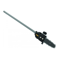
Installing the Guide Bar and Saw Chain
(Fig. A, D–G)
CAUTION: Sharp chain. Always wear protective gloves
when handling the chain. The chain is sharp and can cut
you when it is notrunning.
WARNING: Sharp moving chain. To prevent accidental
operation, ensure that battery is removed from the tool
before performing the following operations. Failure to do
this could result in serious personalinjury.
If the saw chain
7
and guide bar
6
are packed separately in the
carton, the chain has to be attached to the bar, and both must
be attached to the body of thetool.
1. Place the pole saw attachment
1
on a flat, firmsurface.
2. Rotate the bar lock nuts
3
counterclockwise with a 13mm
wrench (not provided) and removethem.
3. Using a flat-head screwdriver rotate the sprocket cover
screw
20
counterclockwise and removeit.
4. Take off the sprocket cover
2
.
5. Using a flat-head screwdriver turn chain tensioning screw
8
counterclockwise fourturns.
6. Wearing protective gloves, grasp the saw chain
7
and wrap
it around the guide bar
6
, ensuring the teeth are facing the
correctdirection.
7. Ensure the chain is properly set in the slot around the entire
guidebar.
DISASSEMBLY
WARNING: To reduce the risk of serious personal
injury, turn unit off and remove the battery pack
before making any adjustments or removing/
installing attachments or accessories. An accidental
start‑up can causeinjury.
Detaching Pole Saw Assembly (Fig. B, C, K)
WARNING: Sharp moving blade. To prevent accidental
operation, insure that battery is disconnected from the
handle and that the protective scabbard is in place on the
chain before performing the following operations. Failure
to do this could result in serious personal injury.
When detaching the assemblies, always detach the pole saw
attachment
1
first.
To Remove the Extension Pole from the Pole
SawAttachment:
1. Install scabbard
14
on guide bar andchain.
2. When removing the pole saw attachment
1
from the
extension pole
17
, loosen the knob
13
.
3. Depress the latching button
18
located on the extension
pole coupler
12
, and pull the pole saw attachment
1
away
from the extension pole
11
.
To Remove the Powerhead from the extension pole:
1. When removing the extension pole
11
from the
powerhead
17
, loosen the knob
13
. Then depress the
latching button
18
and pull the extension pole
11
away
from the powerhead
17
.
Combining the powerhead
17
to the pole saw attachment
1
creates a pole saw that is approximately 1.8m in length.
To Attach the Powerhead to the Pole Saw Attachment:
1. When installing the pole saw attachment
1
into the upper
powerhead pole
17
, align the latching button
18
with the
main hole
19
as shown in Fig. B.
2. Turn the knob
13
clockwise to lock attachment to upper
powerheadpole. When properly assembled, it should look
like Fig. B. If it does not, do not use, disassemble and re-align
the pole saw attachment
1
so the latching button
18
engages the hole
19
.
WARNING: Always check to make sure that the knobs
are completely secured in place. If the knobs are not
completely secured it could result in the assemblies
becoming disconnected creating a hazardous condition.
Periodically check the connections to ensure that the
knobs are completely secured inplace.
Assembling the Extension Pole to the
Pole Saw Attachment and the Powerhead
(Fig. B, C)
To Attach the Powerhead to the Pole Saw Attachment:
Adding the extension pole
11
to the powerhead
17
and pole
saw attachment
1
creates a pole saw that is approximately
2.7m in length.
To Attach the Powerhead to the Extension Pole and Pole
Saw Attachment:
1. When installing the extension pole
11
into the upper
powerhead pole
17
, align the latching button
18
with the
main hole
19
as shown in Fig. B.
2. Turn the knob
13
clockwise to lock attachment to upper
powerheadpole.
To Attach the Pole Saw Attachment to the Extension Pole:
1. When installing the pole saw attachment
1
into the extension
pole
11
, align the latching button
18
with the hole
19
on
the extension pole coupler
12
as shown in Fig.C
2. Turn the knob
13
clockwise to lock attachment to upper
powerheadpole.
3. When properly assembled, it should look like Fig.C. If it
does not, do not use, disassemble and re-align the pole
saw attachment
1
so the latching button
18
engages the
hole
19
in the extension pole coupler
12
.
WARNING: Always check to make sure that the knobs
are completely secured in place. If the knobs are not
completely secured it could result in the assemblies
becoming disconnected creating a hazardous condition.
Periodically check the connections to ensure that the
knobs are completely secured inplace.