14
ENGLISH
unless they are supervised by a person responsible for their
safety. Children should never be left alone with thisproduct.
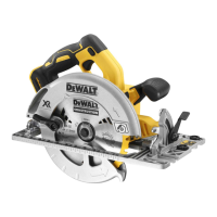
Saw Hook (Fig. C)
WARNING: To reduce the risk of serious personal injury,
Do not use the saw with the saw hook rotated below the
footplate.
WARNING: To reduce the risk of injury from the saw
falling on operators or bystanders, make sure the saw is
supported securely when using the hook to hang the saw
from a rafter, joist or other elevatedsupport.
Your saw has a convenient saw hook
23
that allows the saw to
hang from a joist, rafter, or other suitable, stable structure. The
saw hook folds flat against the tool body when not inuse.
To use the saw hook, push down on the hook to rotate it away
from the handle until it latches intoposition.
To return the saw hook to its stored position, pull the hook up
until it latches against the toolbody.
ASSEMBLY AND ADJUSTMENTS
WARNING: To reduce the risk of serious personal
injury, turn tool off and disconnect battery pack
before making any adjustments or removing/
installing attachments or accessories. An accidental
start-up can causeinjury.
WARNING: Use only
battery packs andchargers.
Inserting and Removing the Battery Pack
from the Tool (Fig. B)
NOTE: Make sure your battery pack
15
is fullycharged.
To Install the Battery Pack into the Tool
1. Align the battery pack
15
with the rails inside the tool
(Fig.B).
2. Slide it in until the battery pack is firmly seated in the tool
and ensure that you hear the lock snap intoplace.
To Remove the Battery Pack from the Tool
1. Press the release button
14
and firmly pull the battery pack
out of thetool.
2. Insert battery pack into the charger as described in the
charger section of thismanual.
Fuel Gauge Battery Packs (Fig. B)
Some
battery packs include a fuel gauge which
consists of three green LED lights that indicate the level of
charge remaining in the batterypack.
To actuate the fuel gauge, press and hold the fuel gauge button.
A combination of the three green LED lights will illuminate
designating the level of charge left. When the level of charge
in the battery is below the usable limit, the fuel gauge will not
illuminate and the battery will need to berecharged.
NOTE: The fuel gauge is only an indication of the charge left on
the battery pack. It does not indicate tool functionality and is
subject to variation based on product components, temperature
and end-userapplication.
Cutting Depth Adjustment (Fig. A, D, E)
1. Hold the saw firmly. Lift the depth adjustment locking
lever
3
to move foot plate to obtain the desired depth
ofcut.
2. Lower the depth adjustment locking lever and tighten
securely to lock the depth of cut before operatingsaw.
The length of cut markings on the side of the foot plate are
accurate at full depth of cut only. Setting the saw at the proper
cutting depth keeps blade friction to a minimum, removes
sawdust from between the blade teeth, results in cooler, faster
sawing and reduces the chance ofkickback.
For the most efficient cutting action, set the depth adjustment
so that half of a blade tooth will project below the material
to be cut (refer to Figure E). This distance is from the tip of
the tooth
31
to the bottom of the gullet
32
(refer to inset
of FigureE). This keeps blade friction at a minimum, removes
sawdust from the cut, results in cooler, faster sawing and
reduces the chance of kickback. A method for checking for
correct cutting depth is shown in FigureE. Lay a piece of the
material you plan to cut along the side of the blade, as shown,
and observe how much tooth projects beyond thematerial.
Mounting the Dust Extraction Port (Fig. U, V)
WARNING: The dust extraction port must be installed
onto the saw before use.
WARNING: Risk of dust inhalation. To reduce the risk of
personal injury, ALWAYS wear an approved dustmask.
1. Align the dust extraction port
20
over upper blade guard
34
as shown.
2. Insert the two dust port screws
37
through the dust port
holes
36
and into the upper blade guard holes
35
as show
in Figure A and tighten securely.
The dust extraction adaptor allows you to connect the tool to
an external dust extractor, either using the AirLock™ system
(DWV9000-XJ), or a standard 35mm dust extractorfitment
(Fig.V).
WARNING: ALWAYS use a vacuum extractor designed
in compliance with the applicable directives regarding
dust emission when sawing wood. Vacuum hoses of most
common vacuum cleaners will fit directly into the dust
extractionoutlet.
Bevel Angle Adjustment (Fig. A, F)
The full range of the bevel adjustment is from 0˚ to 53˚.
Detents are located at 22.5˚ and 45˚. The angle quadrant
is graduated in increments of 1˚. On the front of the saw is
a bevel angle adjustment mechanism which consists of a
calibrated angle quadrant
10
and a bevel adjustment lever
9
.
The angle quadrant allows for coarse adjustment
16
or fine
adjustment
17
to achieve better accuracy incutting.
To Set the Saw for a Bevel Cut
1. Lift the bevel adjustment lever
9
and tilt foot plate to the
desired angle by aligning the pointer with the desired
anglemark.