ENGLISH
15
Fig. R
Place the work with its “good” side – the one on which
appearance is most important – down. The saw cuts
upward, so any splintering will be on the work face that is
up when you cutit.
Cutting (Fig. P)
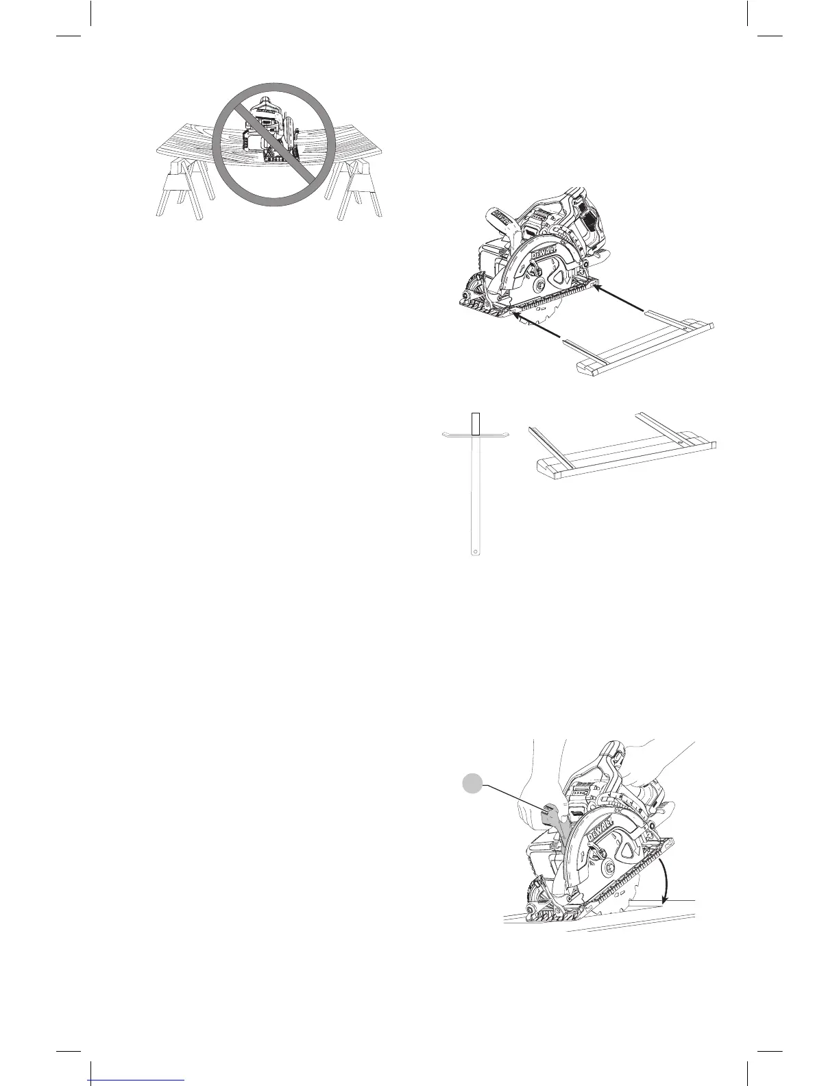
WARNING: Never attempt to use this tool by resting
it upside down on a work surface and bringing
the material to the tool. Always securely clamp
the workpiece and bring the tool to the workpiece,
securely holding the tool with two hands as shown
in FigureP.
Place the wider portion of the saw foot plate on that part
of the work piece which is solidly supported, not on the
section that will fall off when the cut is made. As examples,
FigureP illustrates the RIGHT way to cut off the end of a
board. Always clamp work. Don’t try to hold short pieces by
hand! Remember to support cantilevered and overhanging
material. Use caution when sawing material frombelow.
Be sure saw is up to full speed before blade contacts
material to be cut. Starting saw with blade against material
to be cut or pushed forward into kerf can result in kickback.
Push the saw forward at a speed which allows the blade
to cut without laboring. Hardness and toughness can vary
even in the same piece of material, and knotty or damp
sections can put a heavy load on the saw. When this
happens, push the saw more slowly, but hard enough to
keep working without much decrease in speed. Forcing
the saw can cause rough cuts, inaccuracy, kickback, and
over-heating of the motor. Should your cut begin to go
off the line, don’t try to force it back on. Release the switch
and allow blade to come to a complete stop. Then you can
withdraw the saw, sight anew, and start a new cut slightly
inside the wrong one. In any event, withdraw the saw if you
must shift the cut. Forcing a correction inside the cut can
stall the saw and lead tokickback.
IF SAW STALLS, RELEASE THE TRIGGER AND BACK THE SAW
UNTIL IT IS LOOSE. BE SURE BLADE IS STRAIGHT IN THE CUT
AND CLEAR OF THE CUTTING EDGE BEFORERESTARTING.
As you finish a cut, release the trigger and allow the blade
to stop before lifting the saw from the work. As you lift
the saw, the spring-tensioned telescoping guard will
automatically close under the blade. Remember the blade
is exposed until this occurs. Never reach under the work for
any reason. When you have to retract the telescoping guard
manually (as is necessary for starting pocket cuts) always
use the retractinglever.
NOTE: When cutting thin strips, be careful to ensure that
small cutoff pieces don’t hang up on inside of lowerguard.
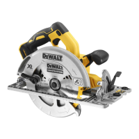
Ripping (Fig. S, T1, T2)
Ripping is the process of cutting wider boards into narrower
strips – cutting grain lengthwise. Hand guiding is more
difficult for this type of sawing and the use of either
DW3278 rip guide (Fig. T1) or DWS5100 dual port rip guide
is recommended (Fig.T2).
Fig. S
Fig. T1
Fig. T2
DW3278
DWS5100
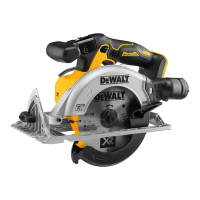
Pocket Cutting (Fig. U)
WARNING: Never tie the blade guard in a raised
position. Never move the saw backwards when
pocket cutting. This may cause the unit to raise
up off the work surface which could causeinjury.
A pocket cut is one that is made in a floor, wall, or other
flatsurface.
Fig. U
13
1. Adjust the saw foot plate so the blade cuts at
desireddepth.
2. Tilt the saw forward and rest front of the foot plate on
material to becut.