16
ENGLISH
• Young children and the infirm. This appliance is not
intended for use by young children or infirm persons
withoutsupervision.
• This product is not intended for use by persons (including
children) suffering from diminished physical, sensory or
mental abilities; lack of experience, knowledge or skills
unless they are supervised by a person responsible for their
safety. Children should never be left alone with thisproduct.
ASSEMBLY AND ADJUSTMENTS
WARNING: To reduce the risk of serious personal
injury, turn tool off and disconnect battery pack
before making any adjustments or removing/
installing attachments or accessories. An accidental
start-up can causeinjury.
WARNING: Use only
battery packs andchargers.
Inserting and Removing the Battery Pack
from the Tool (Fig. B)
NOTE: Make sure your battery pack
12
is fullycharged.
To Install the Battery Pack into the
Machine
1. Align the battery pack with the rails inside themachine.
2. Slide it into the machine until the battery pack is firmly
seated in the tool and ensure that you hear the lock snap
intoplace.
To Remove the Battery Pack from the
Machine
1. Press the release button
13
and firmly pull the battery pack
out of themachine.
2. Insert battery pack into the charger as described in the
charger section of thismanual.
Fuel Gauge Battery Packs (Fig. B)
Some
battery packs include a fuel gauge which
consists of three green LED lights that indicate the level of
charge remaining in the batterypack.
To actuate the fuel gauge, press and hold the fuel gauge
button
25
. A combination of the three green LED lights will
illuminate designating the level of charge left. When the level
of charge in the battery is below the usable limit, the fuel gauge
will not illuminate and the battery will need to berecharged.
NOTE: The fuel gauge is only an indication of the charge left on
the battery pack. It does not indicate tool functionality and is
subject to variation based on product components, temperature
and end-userapplication.
Unpacking
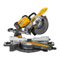
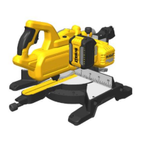
• Remove the saw from the packaging materialcarefully.
• The machine is fully assembled except for the rip fence,
mitre gauge, dust adapter and blade guardassembly.
• Finalise the assembly following the instructions as
describedbelow.
Mounting the Saw Blade (Fig. A, C)
WARNING: To reduce the risk of injury, turn unit
off and disconnect machine from power source
before installing and removing accessories, before
adjusting or changing set-ups or when making
repairs. Be sure the trigger switch is in the OFF position.
An accidental start-up can causeinjury.
WARNING: The teeth of a new blade are very sharp and
can bedangerous.
WARNING: The saw blade MUST be replaced as described
in this section. ONLY use saw blades as specified under
Technical Data. We suggest DT99565. NEVER fit other
sawblades.
NOTE: This tool has blade installed fromfactory.
1. Raise the saw blade arbor to its maximum height by turning
the blade height adjustment wheel
6
clockwise.
2. Remove the throat plate
17
. Refer to Mounting the
throatplate.
3. Using wrenches
21
, loosen and remove the arbor nut
26
and clamp washer
27
from the saw arbor by turning anti-
clockwise.
4. Place the saw blade on to the arbor
28
making sure the
teeth of the blade
2
point down at the front of the table.
Assemble the washers and arbor nut to the spindle and
tighten arbor nut
26
as far as possible by hand, making
sure that the saw blade is against the inner washer and the
outer clamp washer
27
is against the blade. Ensure the
largest diameter of the flange is against the blade. Ensure
the spindle and washers are free from dust anddebris.
5. To keep the spindle from rotating when tightening the
arbor nut, use the open end of the blade wrench
21
to
secure thespindle.
6. Using the closed end of the blade wrench, tighten the arbor
nut
26
by turning itclockwise.
7. Replace the throatplate.
WARNING: Always check the rip fence pointer and the
blade guard assembly after having changed theblade.
Mounting/Removing the Blade Guard
Assembly/Riving Knife (Fig. A, D)
WARNING: Use the guard assembly for all
throughcutting.
1. Raise the saw blade arbor to its maximumheight.
2. Loosen the riving knife lock knob
29
(minimum of
threeturns).
3. To disengage riving knife lock pin, pull lock knob as
indicated by the black arrows on theknob.
4. While pulling the lock knob, lift the riving knife out of the
clamp. Then slide the blade guard assembly into the clamp
until it bottomsout.
NOTE: Do not install both blade guard assembly and riving
knife into the clamp at the sametime.
5. Release the lock knob to engage the lock pin. Give the blade
guard a slight pull upwards to ensure pin is engaged.
Ташев-Галвинг ООД
www.tashev-galving.com