14
DANSK
1. Løsn vinkellåsegrebet
20
og indstil den ønskedevinkel.
2. Indstil om nødvendigt tilsidesættelsesknappen
31
.
3. Hold hovedet fast og lad det ikkefalde.
4. Spænd vinkellåsegrebet
20
fast.
5. Fortsæt som ved den lige lodretteskæring.
Snitkvalitet
Glatheden af alle snit er afhængigt af adskillige variabler, som f.eks. det
materiale der skæres. Hvis du ønsker meget glatte snit til kantprofiler og
andet præcisionsarbejde, vil en skarp (60-tandet hårdtmetal) klinge og en
langsommere, jævn snithastighed frembringe de ønskederesultater.
ADVARSEL: Kontrollér at materialet ikke kryber under skæring;
fastspænd det godt på plads. Lad altid klingen komme til et fuldt stop,
før armen hæves. Hvis der stadig er små træsplinter, som stikker ud af
enden på arbejdsemnet, skal der anbringes et stykke afdækningstape
på træet, hvor snittet skal være. Sav gennem tapen og fjern
omhyggeligt tapen, når skæringen erafsluttet.
Fastspænding af arbejdsemnet (Fig. T)
ADVARSEL: Brug altid enmaterialeholder.
For at opnå det bedste resultater skal der anvendes en materialeholder
17
,
som er blevet konstrueret til anvendelse med dinsav.
Sådan monteres holderen
1. Indsæt den i hullet bag ved anslaget. Holderen
17
skal vende imod
geringssavens bagside. Kontrollér at rillen på holderstangen er helt
indsat i geringssavens fundament. Hvis rillen er synlig, er holderen ikke
sikkertfastgjort.
2. Drej holderen 180º imod geringssavensforside.
3. Løsn knappen for at justere holderen op eller ned, og anvend derefter
finjusteringsknappen til at fastgørearbejdsemnet.
BEMÆRK: Anbring holderen på højre side af fundamentet under
vinkelskæring. TEST ALTID FØRST MED SLUKKET MASKINE (UDEN STRØM),
INDEN DU UDFØRER SKÆRINGER, SÅ DU KAN KONTROLLERE KLINGENS STI.
HOLDEREN SKAL FASTGØRES SÅLEDES, AT DEN IKKE HAR INDFLYDELSE PÅ
SAVENS ELLER BESKYTTELSESSKÆRMENESFUNKTIONER.
Dobbeltgering (Fig. S)
Denne skæring er en kombination af et gerings- og vinkelsnit. Det er denne
type skæring, der bruges til at lave rammer eller kasser med skrånende sider
som den, der vises i figurS.
ADVARSEL: Hvis skærevinklen varierer fra snit til snit, skal det
kontrolleres at vinkellåsegrebet og geringslåseknappen er spændt
korrekt. De skal spændes fast, efter der er foretaget ændringer af vinkler
ellergering.
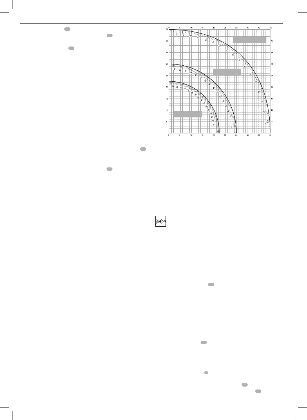
• Efterfølgende skema kan hjælpe dig med at vælge de korrekte vinkel-
og geringsindstillinger til gængsedobbeltgeringssnit.
• For at kunne anvende skemaet skal du vælge den ønskede vinkel "A"
(Fig.S) til dit projekt og finde denne vinkel på den passende kurve i
oversigten. Fra dette punkt skal du følge linjen lige nedad på tegningen
for at finde den korrekte hældningsvinkel og lige tværs over for at finde
den korrektegeringsvinkel.
Indstil denne geringsvinkel på saven
Vinkel på kassens side (vinkel "A")
Indstil denne hældningsvinkel på saven
1. Indstil din sav til de foreskrevne vinkler og foretag et parprøvesnit.
2. Øv dig i at sætte de skårne stykkersammen.
Eksempel: For at lave en 4-sidet kasse med 25º udvendige vinkler
(vinkel "A") (Fig.S) skal den øverste højre kurve anvendes. Find 25°
på kurveskalaen. Følg den vandrette skæringslinje til en af siderne
for at finde geringsvinkelindstillingen på saven (23°). Følg på same
måde den lodrette skæringslinje opad eller nedad for at finde
hældningsvinkelindstillingen på saven (40°). Foretag altid prøvesnit på
nogle stykker affaldstræ
for at kontrollere indstillingerne påsaven.
ADVARSEL: Overskrid aldrig dobbeltgeringsgrænserne på 45° vinkel
med 45° gering til venstre ellerhøjre.
Støvopsamling (Fig. A, G)
ADVARSEL: Tilslut, hver gang det er muligt, en støvopsamlingsenhed,
der er konstrueret i henhold til de relevante bestemmelser med hensyn
tilstøvemission.
Tilslut en støvopsamlingsenhed, der er konstrueret i henhold til de relevante
bestemmelser. Lufthastigheden på eksternt tilsluttede systemer skal
være 20m/sek +/- 2 m/sek. Hastigheden skal måles i tilslutningsrøret på
tilslutningspunktet, med tilsluttet værktøj, men ikke idrift.
BEMÆRK: Det anbefales at anvende en hurtigforbindelse
DWV9000 med drejetilslutning
48
som valgfrit tilbehør til at
tilsluttestøvopsamlingsenheden.
Overhold de relevante bestemmelser i dit land for de materialer, der
skalbearbejdes.
Støvsugeren skal være egnet til det materiale, derbearbejdes.
Ved støvsugning af tørt støv, der er særligt sundhedsskadeligt eller
kræftfremkaldende, skal der anvendes en specielstøvsuger.
Transport (Fig. A, B)
ADVARSEL: For at kunne bære geringsaven komfortabelt findes
der to fordybninger
32
til hænderne i bunden. Anvend aldrig
beskyttelsesskærme til at løfte eller transporteregeringsaven.
1. Når saven skal transporteres skal hældningsvinkel- og
geringspositionerne indstilles til 0°.
2. Skub savhovedet helttilbage.
3. Tryk på frigørelsesgrebet
2
til spærremekanismen for den nedre
beskyttelsesskærm (Fig.A).
4. Tryk hovedet nedad og tryk på spærreknappen
23
(Fig.B).
5. Bring savklingen i hvileposition og tryk på tværspærren
18
.
8-SIDET KASSE
FIRKANTET KASSE
6-SIDET KASSE
 Loading...