WARNING: To reduce the risk of serious personal injury, turn unit off and remove the battery pack before making any adjustments or
removing/ installing attachments or accessories. An accidental start‑up can cause injury. The powerhead can separate from the attachment by
turning the knob 20 counterclockwise, depressing the latching button 21 and gently pulling them apart by their poles 1 , 19 .
This should only be done with the power switch off and the battery pack removed. Inside the upper powerhead pole 19 is a mechanical coupling
that will spin if the powerhead is turned on. This coupling can cause injury if contacted while the powerhead is operating. Arrows 12 must align
for proper assembly of most attachments. See specific attachment instructions for details.
NOTE: Ensure the attachment is fully engaged and the knob is fully tightened before operating. Check for proper engagement and tightness
during use.
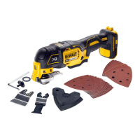
Attachments
WARNING: This powerhead is only to be used with DEWALT attachments. Use of attachments that are not recommended for use may
increase risk of injury.
WARNING: Read the entire instruction manual for each optional attachment prior to using with this powerhead. This powerhead has been
designed for the purpose of residential lawn and garden maintenance. It is recommended for use with DeWALT attachments.
DO NOT use this powerhead or any attachment for anything other than its intended use described in this and the attachments instructions. For a
complete list of recommended attachments contact customer service.
Assembling the Attachment to the Powerhead (Fig. B)
1. The upper powerhead pole 7 is equipped with three latching holes 8, 9, 10 for the latching button 21.
2. When installing attachment pole 5 into the upper powerhead pole 7, align the latching button 21 with the correct latching hole 8. See specific
attachment instructions for details.
NOTE: To properly engage the latching button 21 with the latching hole 8, slightly rotate the powerhead pole 7 and move it axially until the
latching button engages the latching hole.
3. Turn the knob 20 to secure the attachment.
4. See the attachment instructions for properly assembled attachment.
OPERATION
WARNING: To reduce the risk of serious personal injury, turn unit off and remove the battery pack before making any adjustments or removing/
installing attachments or accessories. An accidental start‑up can cause injury.
WARNING: Read the entire instruction manual for each optional attachment prior to using with this powerhead.
Installing and Removing the Battery Pack (Fig. E)
NOTE: For best results, make sure your battery pack is fully charged. To install the battery pack 7 into the tool handle, align the battery pack with the
rails inside the tool’s handle and slide it into the handle until the battery pack is firmly seated in the tool and ensure that it does not disengage. To
remove the battery pack from the tool, press the release button 8 and firmly pull the battery pack out of the tool handle. Insert it into the charger as
described in the charger section of this manual.
Proper Hand Position (Fig. J)
WARNING: To reduce the risk of serious personal injury, ALWAYS use proper hand position as shown.
WARNING: To reduce the risk of serious personal injury, ALWAYS hold securely in anticipation of a sudden reaction.
WARNING: Hold the tool using only the designated gripping surfaces: The powerhead handle and the auxiliary handle.
WARNING: Do not use the pole as a gripping surface. Proper hand position requires one hand on the powerhead handle 4 and one hand on
the auxiliary handle 6.
Switching On and Off (Fig. A, G)
1. To turn the appliance on, push the lock-off tab 3 forward, squeeze the lock-off lever 2 and then the variable speed trigger switch 1 .
2. To turn the appliance off, release the variable speed trigger switch and lock-off lever.
WARNING: Never attempt to lock the trigger in the on position. Speed Control Switch (Fig. A, G)
This powerhead gives you the choice to operate at a more efficient speed to extend the runtime for larger jobs, or accelerate the tool speed for high-
performance needs.
1. To extend runtime, pull the speed control switchback toward the battery housing into the “LO” position. This mode is best for larger projects that
require more time to complete.
2. For high‑performance, push the speed control switch forward toward the auxiliary handle into the “HI” position. This mode is best to for
applications that need higher RPM.
NOTE: When in “HI” mode, the runtime will be decreased as compared to when trimmer is in “LO” mode.
MAINTENANCE

 Loading...