ENGLISH
12
5
12
11
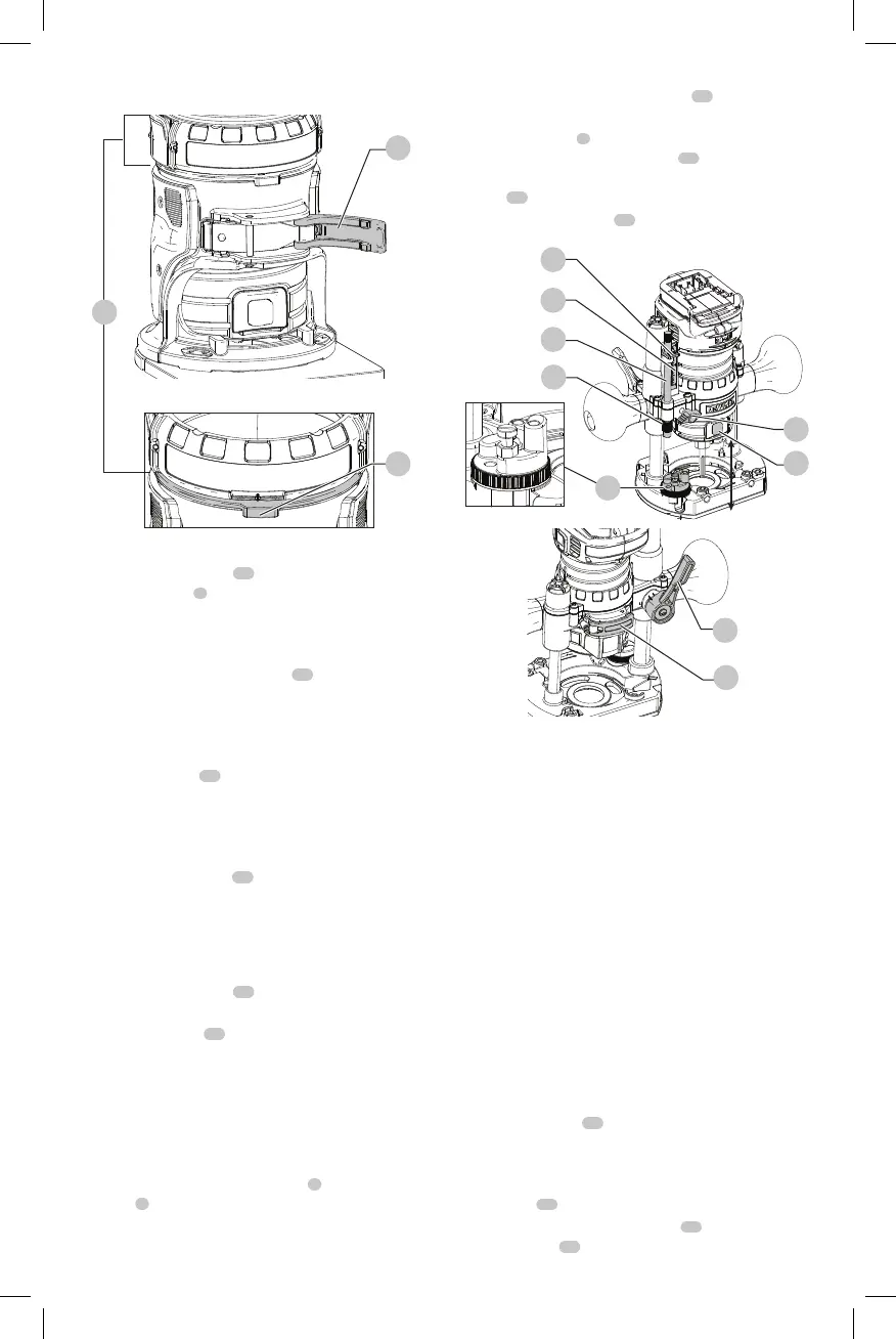
Fig. L
Adjusting the Depth of Cut (Fig. L)
1. Open the locking lever
12
and turn the depth
adjustment ring
5
until the bit just touches the work
piece. Turning the ring clockwise raises the cutting
head while turning it counterclockwise lowers the
cuttinghead.
2. Turn the micro-adjustment scale
11
clockwise until the
0 on the scale lines up with the pointer on the bottom
of the depth adjustmentring.
3. Turn the depth adjustment ring until the pointer lines
up with desired depth of cut marking on the micro-
adjustment scale
11
.
NOTE: Each mark on the adjustment scale represents
a depth change of 1/64" or .015" (0.4 mm) and one
full (360º) turn of the ring changes the depth 0.5"
(12.7mm).
4. Close the locking lever
12
to lock thebase.
Removing the Motor from the Fixed
Base (Fig. K)
1. Remove the battery pack from the motor. Refer to
Installing and Removing the BatteryPack.
2. Open the locking lever
12
on thebase.
3. Grasp the motor unit with one hand, depressing both
quick release tabs
21
.
4. With the other hand, grasp the base and pull motor
from thebase.
Set-up: Plunge Base (Fig. A, M)
Inserting the Motor into the Plunge
Base
1. Remove the depth adjustment ring
5
from the
motor
6
. It is not used with the plunge base.
NOTE:Snap depth adjustment ring onto fixed base,
when not in use, to preventloss.
2. Open the plunge base locking lever
39
.
3. Making sure the spindle lock button is facing front,
insert the motor
6
into the base by aligning the groove
on the motor with the guide pins
17
on the base. Slide
the motor down until the motor stops on the motor
stop
19
.
4. Close the locking lever
39
.
Fig. M
40
7
15
14
41
42
43
39
16
Adjusting the Plunge Routing Depth
(Fig. M)
WARNING: Laceration hazard. Do not change the
turret stop while the router is running. This will
place your hands too near the cutterhead.
WARNING: To prevent loss of control, ALWAYS
tighten the travel-limiting nuts together.
Inadvertent movement could prevent full
bitretraction.
WARNING: To prevent loss of control, set
the travel-limiting nuts so that bit can be
retracted into the base of the router, clear of
theworkpiece.
WARNING: To reduce the risk of injury, NEVER
adjust or remove the stop nut. Motor can
disengage resulting in loss ofcontrol.
CAUTION: Turn the router on before plunging the
cutter head into theworkpiece.
1. Unlock the plunge mechanism by pulling down the
plunge lock lever
16
. Gently push down on the two
handes to plunge the router down as far as it will go,
allowing the bit to just touch theworkpiece.
2. Lock the plunge mechanism by releasing the plunge
lock lever
16
.
3. Loosen the depth adjustment rod
15
by turning the
thumb screw
40
counterclockwise.

 Loading...