ENGLISH
4
more than one extension to make up the total length,
be sure each individual extension contains at least the
minimum wire size. The following table shows the correct
size to use depending on cord length and nameplate
ampere rating. If in doubt, use the next heavier gauge. The
lower the gauge number, the heavier thecord.
Minimum Gauge for Cord Sets
Volts
Total Length of Cord in Feet
(meters)
120 V 25 (7.6) 50 (15.2) 100 (30.5) 150 (45.7)
240 V 50 (15.2) 100 (30.5) 200 (61.0) 300 (91.4)
Ampere Rating
American Wire Gauge
More
Than
Not
More
Than
0 6 18 16 16 14
6 10 18 16 14 12
10 12 16 16 14 12
12 16 14 12 Not Recommended
The label on your tool may include the following symbols. The
symbols and their definitions are asfollows:
V ......................... volts
Hz .......................hertz
min ..................... minutes
or DC ......direct current
...................... Class I Construction
(grounded)
…/min ..............per minute
BPM .................... beats per minute
IPM ..................... impacts per minute
RPM .................... revolutions per
minute
sfpm ................... surface feet per
minute
SPM .................... strokes per minute
A ......................... amperes
W ........................watts
or AC ...........alternating current
or AC/DC .... alternating or
direct current
...................... Class II
Construction
(double insulated)
n
o
.......................no load speed
n .........................rated speed
......................earthing terminal
.....................safety alert symbol
.....................visible radiation
..................... wear respiratory
protection
..................... wear eye
protection
..................... wear hearing
protection
..................... read all
documentation
SAVE THESE INSTRUCTIONS FOR
FUTURE USE
Motor
Be sure your power supply agrees with the nameplate
marking. Voltage decrease of more than 10% will cause loss
of power and overheating.
tools are factory tested;
if this tool does not operate, check powersupply.
Intended Use
These heavy-duty hammerdrills are designed for
professional drilling and hammerdrilling. DO NOT use
under humid conditions or in presence of flammable liquids
orgases.
NOTICE: Not recommended for mixingapplications.
These heavy-duty hammerdrills are professional power
tools. DO NOT let children come into contact with the tool.
Supervision is required when inexperienced operators use
thistool.
DO NOT use under wet conditions or in presence of
flammable liquids orgases.
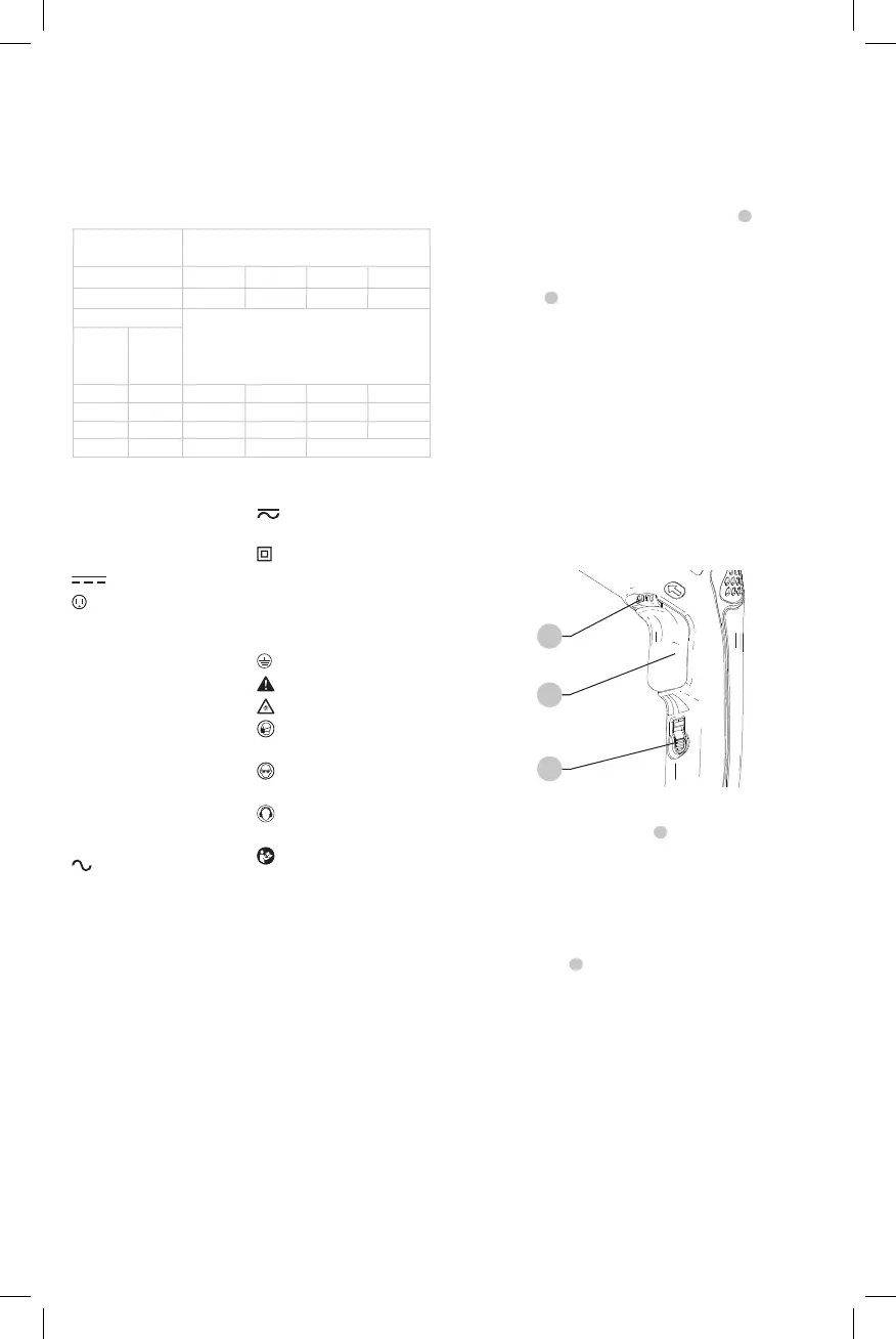
Switch (Fig. B)
To start hammerdrill, depress the trigger switch
1
. To stop
hammerdrill, release theswitch.
To lock the trigger switch in the ON position for continuous
operation, depress the trigger switch and push up the
locking button
2
. The tool will continue torun.
To turn the tool OFF from a locked on condition, squeeze
and release the trigger once. Before using the tool (each
time), be sure that the locking button release mechanism is
workingfreely.
The locking button is for use only when the hammerdrill is
mounted in a drill press stand or otherwise held stationary.
Do not lock the switch ON when drilling by hand so that
you can instantly release the trigger switch if the bit binds in
the hole. Be sure to release the locking mechanism before
disconnecting the plug from the power supply. Failure to do
so will cause the hammerdrill to start immediately the next
time it is plugged in. Damage or injury couldresult.
Fig. B
3
1
2
Variable Speed Trigger Switch (Fig. B)
The variable speed trigger switch
1
permits speed control.
The farther the trigger switch is depressed, the higher the
speed of thehammerdrill.
NOTE: Use lower speeds for starting holes, drilling in plastics
or ceramics or drivingscrews.
Reversing Lever (Fig. B)
The reversing lever
3
, located above the trigger switch,
changes the direction of rotation of the hammerdrill and is
used when backing out screws and jammed drillbits.
To operate the tool in reverse, release the trigger switch
and push the lever to the left (when viewed from the
chuckend).
To operate the drill in forward, release the trigger switch
and push the lever to the right (when viewed from the
chuckend).
Return the reversing lever to the forward position after all
operations in reverse arecompleted.