27
ENGLISH
10
Dust extraction adapter
11
Fixed upper blade guard
12
Moveable lower blade guard
13
Guard release lever
14
Operating handle
A2
14
Operating handle
15
Trigger switch (mitre saw mode)
16
Riving knife storage
17
Push stick storage
18
Leg
19
Foot
20
Table locking device
21
Saw table retention bracket
22
Bevel clamp handle
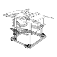
BENCH SAW MODE
A3
22
Bevel clamp handle
23
Height adjuster
24
Bench saw table
25
Upper blade guard
26
Parallel fence
27
Mitre fence (option)
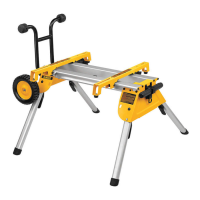
OPTIONAL ACCESSORIES
For use in mitre saw mode:
A4
28
Adjustable stand 760 mm (max. height)
(DE3474)
29
Support guide rails 1,000 mm (DE3494)
Support guide rails 500 mm (DE3491)
30
Swivelling stop (DE3462)
31
Length stop for short workpieces (to be
used with guide rails
29
) (DE3460)
32
Support with removable stop (DE3495)
33
Support with stop removed (DE3495)
34
Material clamp (DE3461)
A5
35
Roller support table (DE3497)
For use in bench saw mode:
A3
27
Mitre fence (DE3496)
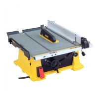
A6
36
Extension table (DE3472)
A7
37
Single sliding table (DE3471)
NOT SHOWN
- Double sliding table
FOR USE IN ALL MODES:
A8
38
Three way dust extraction kit (DE3500)
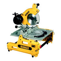
Intended Use
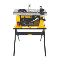
Your
flip-over saw has been designed to operate as a mitre saw or saw bench to
perform the four main sawing operations of ripping, cross-cutting, bevelling and mitring
easily, accurately andsafely.
This unit is designed for use with a nominal blade diameter 250 mm carbide tip blade for
professional cutting wood, wood products andplastics.
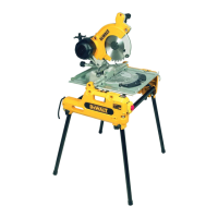
Mitre Saw Mode
In mitre saw mode, the sawing machine is used in vertical, mitre or bevelposition.
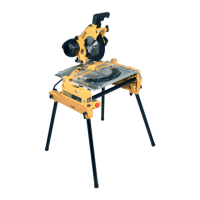
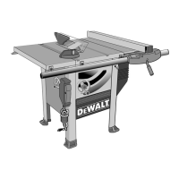
Bench Saw Mode
Turned over on its central axis, the sawing machine is used to perform the standard ripping
operation and for sawing wide pieces by manually feeding the workpiece into theblade.
WARNING: Do not use the machine for other purposes asdescribed.
DO NOT use under wet conditions or in the presence of flammable liquids orgases.
DO NOT let children come into contact with the tool. Supervision is required when
inexperienced operators use thistool.
• Young children and the infirm. This appliance is not intended for use by young children
or infirm persons without supervision.
• This product is not intended for use by persons (including children) suffering from
diminished physical, sensory or mental abilities; lack of experience, knowledge or skills
unless they are supervised by a person responsible for their safety. Children should never
be left alone with thisproduct.
ASSEMBLY AND ADJUSTMENTS
WARNING: To reduce the risk of injury, turn unit off and disconnect machine
from power source before installing and removing accessories, before adjusting
or changing set-ups or when making repairs. Be sure the trigger switch is in the OFF
position. An accidental start-up can causeinjury.
Unpacking
WARNING: When moving the machine, always seek assistance. The machine is too heavy
for one person tohandle.
1. Remove the loose packaging material from thebox.
2. Lift the machine out of thebox.
3. Remove the parts box from the interior of themachine.
4. Remove any remaining packing material from themachine.
Mounting the Legs (Fig. C1)
With the legs mounted, the machine is suitable for stand-aloneplacement.
1. Turn the machine upsidedown.
2. Pass a coach bolt
47
from the flat side through the holes into each of the legs
18
.
3. Place a lock knob
48
and washer
49
onto thebolts.
4. Present a leg
18
to each of the mounting points
46
located at the edges on the inside of
the base. For each leg, make sure that the lock knob and washer locate at the outside of
the open endedslot.
5. Tighten the lockknobs.
6. Turn the machine straight up. Make sure it is level; adjust the leg clamping height
ifrequired.
Mounting the Machine to the Workbench (Fig. C2)
With the legs removed, the machine is suitable for placement on a workbench. To ensure a
safe operation, the machine has to be fixed to the workbench and mounted with bolts 8 mm
diameter by 80 mmlong.
Assembly for Mitre Saw Mode
Mounting the Under-table Guard (Fig. D)
The under-table guard
50
is fitted to the top of the bench sawtable.
1. Place the two hooks on the left of the guard into the oblong slots on the left of the blade
slot
52
.
2. Place the guard flat on the table and press it in the lockinggrommet.
3. To remove, loosen the grommet with a screwdriver and proceed in reverseorder.
Turning the Sawhead and Table Over (Fig. A3, E1, E2)
1. Withhold the saw table with one hand and push the table release lever
2
to the left
(Fig.E1).
2. Push the table downwards at the front and swing it over completely until the motor
assembly is uppermost and the indentation engages in the retaining teeth of the table
locking device
20
.
3. The head assembly is held down by a clamp strap at the front and a height adjuster
23
at
the rear (Fig. A3).
4. Remove thestrap.
5. Rotate the wheel
55
counterclockwise whilst holding down the head until the
"U"-shaped bracket
56
can be disengaged from its seating (Fig. E2).
6. Swing and push the height adjusterup.
7. Holding the head firmly, allow the spring pressure to take the head upwards into its
restposition.
Mounting the Saw Blade (Fig. A1, A2, F1–F3)
WARNING: To reduce the risk of injury, turn unit off and disconnect machine
from power source before installing and removing accessories, before adjusting
or changing set-ups or when making repairs. Be sure the trigger switch is in the OFF
position. An accidental start-up can causeinjury.
WARNING: Be aware the saw blade shall be replaced in the described way only. Only use
saw blades as specified under Technical Data; Cat.no.:DT4321.
WARNING: The teeth of a new blade are very sharp and can bedangerous.
WARNING: Always change blades with the machine in mitre sawmode.
1. Ensure riving knife
16
is secured in the upper rest position (Fig. A2).
2. Insert the hex key
57
through the hole
58
in the belt casing into the spindle end (Fig.F1).
Place the blade spanner
59
onto the blade locking screw
60
(Fig. F2).
3. The blade locking screw has a left-handed thread, therefore holding the hex key firmly,
turn the spanner clockwise toloosen.
4. Depress the head lock up guard release lever
13
to release the lower guard
12
, then raise
the lower guard as far aspossible.
5. Remove the blade locking screw
60
and the outside arbor collar
61
(Fig. F3).
6. Make sure the inner flange and both faces of the blade are clean and free ofdust.
7. Install the saw blade
62
onto the shoulder
63
provided on the inside arbor collar
64
,
making sure that the teeth at the bottom edge of the blade are pointing toward the back
of the saw (away from the operator).
8. Carefully ease the blade into position and release the lower bladeguard.
9. Replace the outer arborcollar.
10. Tighten the blade locking screw
60
by turning counterclockwise while holding the hex
key steady with your otherhand.
11. Place the blade spanner and Hex key in their storageposition.
WARNING: After mounting or replacing the blade, always check that the blade is fully
covered by the guard. Make sure the blade spanner and hex key have been replaced in
their storageposition.
Adjustments for Mitre Saw Mode
WARNING: Be aware the saw blade shall be replaced in the described way only. Only use
saw blades as specified under Technical Data; Cat.no.:DT4321.
Your mitre saw was accurately adjusted at the factory. If readjustment due to shipping and
handling or any other reason is required, follow the steps below to adjust your saw. Once
made, these adjustments should remainaccurate.
Checking and Adjusting the Blade to the Fence (Fig. G1, G2, H)
With the head in the vertical position and the bevel clamp handle
22
released, slacken the
locking screw
65
in the rotating table location plunger
8
(Fig. G1).
1. Pull down the head until the blade just enters the sawkerf.
2. Place a square
66
against the left side
7
of the fence and blade
62
(Fig. G2). The angle
should be 90°.
WARNING: Do not touch the tips of the blade teeth with thesquare.
3. If adjustment is required, proceed as follows:
a. Rotate the eccentric adjustment bush
67
until the face of the saw blade is flat against
the square (Fig. G1).
b. Tighten the locking screw
65
.
 Loading...