30
ENGLISH
Optional Attachments
WARNING: Prior to assembling any accessories always unplug themachine.
WARNING: Since accessories, other than those offered by D
WALT, have not been tested
with this product, use of such accessories with this tool could be hazardous. To reduce the
risk of injury, only D
WALT, recommended accessories should be used with thisproduct.
Dust Extraction Kit (Fig. A1, A2, A8)
This machine is provided with three dust extraction points for use in mitre mode and two in
benchmode.
• When sawing wood, always connect a dust extraction device designed in accordance with
the relevant regulations regarding dustemission.
WARNING: Whenever possible, connect a dust extraction device designed in accordance
with the relevant regulations regarding dustemission.
Connect a dust collection device designed in accordance with the relevent regulations. The air
velocity of externally connected systems shall be 20 m/s +/- 2 m/s. Velocity to be measured in
connection tube at the point of connection, with the tool connected but notrunning.
A seperate dust kit is available as an option (DE3500)
1. Fit the dust extraction tube to the nozzles; the longer hose to uppernozzle.
2. Connect the hoses to the three wayconnector.
Connecting - Mitre Saw Position
1. Connect one hose to the under-tableguard.
2. Connect one hose to the small diameter outlet and one to the large diameter outlet using
the correspondingspouts.
3. Connect the hoses to the 3-wayconnector.
4. Connect the single outlet of the 3-way connector to the hose from the dustextractor.
Connecting - Bench Saw Position
1. Connect one hose to the small diameter outlet and one to the large diameter using the
correspondingspouts.
2. Blank off the middle opening of the 3-wayconnector.
3. Connect both hoses to the outeroutlets.
Mitre Saw Extra Support/Length Stop (Fig. A4)
The extra support and length stop can be mounted on the left-hand side or on the right-hand
side, or with two sets on eitherside.
1. Fit the items
28
–
34
onto the two guide rails
29
.
2. Use the swivelling stop
30
for cross-cutting 210 mm wide boards (15mmthick).
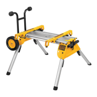
Roller Support Table (Fig. A5)
In mitre saw mode, the roller support table can be mounted on the left-hand side or on the
right-hand side, or with two sets on eitherside.
In bench saw mode, it can also be mounted in front or at the rear of the sawtable.
Side Extension Table (Fig. A6)
The side extension table increases the distance from the rip fence to the blade to 600 mm or
more, depending on the rod length fitted to the machine and the clamped position of the
table. The side extension table must be used in conjunction with guide rails
29
(option).
The adjustable table is equipped with an engraved scale along its front edge and mounted on
a sturdy base which clamps to the guiderods.
• Fit the extension table to the right-hand side of the machine for continuity of the distance
scale on bothtables.
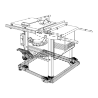
Single Sliding Table (Fig. A7)
This sliding table
37
allows for board sizes to the left of the blade up to 1200 x 900mm.
The guide rods are mounted on a sturdy alloy extrusion which is quickly detachable from the
machine and yet fully adjustable is allplanes.
The fence incorporates a full length measuring tape for quick positioning of an adjustable stop
and an adjustable support for narrowworkpieces.
Double Sliding Table
This sliding table allows for board sizes to the left of the blade up to 1850mm.
Transporting
WARNING: Always transport the machine in bench saw mode with the upper blade
guardfitted.
• Remove thelegs.
WARNING: When carrying the machine, always use the hand indentations (Fig.A1;
40
)
and seek for assistance. The machine could be too wide protruding for one person
tohandle.
MAINTENANCE
Your
power tool has been designed to operate over a long period of time with a
minimum of maintenance. Continuous satisfactory operation depends upon proper tool care
and regularcleaning.
WARNING: To reduce the risk of injury, turn unit off and disconnect machine
from power source before installing and removing accessories, before adjusting
or changing set-ups or when making repairs. Be sure the trigger switch is in the OFF
position. An accidental start-up can causeinjury.
Lubrication
The bearings of the motor are pre-lubricated andwatertight.
• Slightly oil the rotating table bearing surface where it slides on the lip of the fixed table at
regularintervals.
• Clean the parts subject to accumulation of sawdust and chips periodically with a drybrush.
Cleaning
WARNING: Blow dirt and dust out of the main housing with dry air as often as dirt is seen
collecting in and around the air vents. Wear approved eye protection and approved dust
mask when performing thisprocedure.
WARNING: Never use solvents or other harsh chemicals for cleaning the non-metallic
parts of the tool. These chemicals may weaken the materials used in these parts. Use a
cloth dampened only with water and mild soap. Never let any liquid get inside the tool;
never immerse any part of the tool into aliquid.
WARNING: To reduce the risk of injury, regularly clean the tabletop.
WARNING: To reduce the risk of injury, regularly clean the dust collectionsystem.
Before use, carefully check the upper blade guard, movable lower blade guard as well as
the dust extraction tube to determine that it will operate properly. Ensure that chips, dust or
workpiece particle cannot lead to blockage of one of thefunctions.
In case of workpiece fragments jammed between saw blade and guards disconnect the
machine from the power supply and follow the instructions given in section Mounting the
Saw Blade. Remove the jammed parts and reassembling the sawblade.
Optional Accessories
WARNING: Since accessories, other than those offered by
, have not been tested
with this product, use of such accessories with this tool could be hazardous. To reduce the
risk of injury, only
recommended accessories should be used with thisproduct.
Saw Blades
ALWAYS USE noise reduced 250mm SAW BLADES WITH 30mm ARBOR HOLES. SPEED RATING
MUST BE AT LEAST 3000RPM. Never use a smaller or greater diameter blade. It will not be
guarded properly. Use cross cut blades only. Do not use blades designed for fast ripping,
combination blades or blades with hook angles in excess of 10°.
BLADE DESCRIPTIONS
APPLICATION DIAMETER TEETH
Construction Saw Blades (thin kerf with anti-stick rim)
General Purpose 250mm 30 (Series 60)
Woodworking Saw Blades (provide smooth, clean cuts)
Fine crosscuts 250mm 60 (Series 60)
Consult your dealer for further information on the appropriateaccessories.
Protecting the Environment
Separate collection. Products and batteries marked with this symbol must not be
disposed of with normal householdwaste.
Products and batteries contain materials that can be recovered or recycled reducing
the demand for raw materials. Please recycle electrical products and batteries
according to local provisions. Further information is available at www.2helpU.com.
 Loading...