6
English
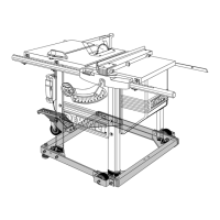
Unpacking
WARNING: To reduce the risk of injury, do not connect the machine to the power
source until the machine is completely assembled and you read and understand the entire
instruction manual.
1. Remove parts box, motor cover, fence beam, side tables and fence rails (DW746X).
2. Turn the saw to the upright position.
CAUTION: Use a minimum of two people to prevent personal injury when turning the saw
and stand upright. The combined weight of the table top and motor assembly is approxi-
mately 200 lbs (91 kg).
3. Cut and remove plastic strap holding the motor.
4. Using front hand crank, lower the motor some and remove the foam packing material
between the motor and the mechanism.
Assembly
WARNING: To reduce the risk of injury, do not connect the machine to the power
source until the machine is completely assembled and you read and understand the entire
instruction manual.
PLEASE READ ENTIRE ASSEMBLY SECTION BEFORE PROCEEDING.
INSTALL BEVEL CRANK (FIG. 2)
1. Install the blade height adjustment wheel (M)
M
AA
BB
FIG. 2
over the shaft (AA), rotate it slightly to fully
engage the shaft pin.
2. Screw the lock knob (BB) into place until it is
fully seated, then back it off 1/4 to 1/2 turn.
3. Turn blade height adjustment wheel (M) to raise
mechanism as high as it will go.
INSTALL WRENCH HOOK (FIG. 3)
NOTE: Always hang the blade wrench, spindle lock
wrench and push stick on wrench hook when not in use.
1. Located the plastic threaded insert at the top of the front right leg.
2. Thread the “L” shaped wrench hook (K) in until only a few threads are
K
FIG. 3
visible.
ASSEMBLE FRONT RAIL AND BRACKETS (FIG. 4)
IMPORTANT: DW746X includes a 30" precision fence rail system. A 30" or
52" precision rail system for the DW746 may be purchased at additional cost. Always fol-
low the instructions included with the accessory. After assembling the rail system, refer to
Parallel the Rails to the Table Top.
If you need assistance with this accessory, please call 1-800-4-D
EWALT (1-800-433-9258)
or visit our website www.dewalt.com.
You will Need: 4 – 8 mm Carriage Bolts
4 – 8 mm Lock Washers
4 – 8 mm Nuts
1. Unpack rail carton (contains front and rear rail).
2. Place the carriage bolts into each rail bracket (CC) as
FIG. 4
DD
CC
shown.
3. Place lock washers and nuts onto carriage bolts and
tighten the nuts a few threads.
4. Place the head of the carriage bolt into keyhole slots in
the front rail and slide to engage the square part of the
bolt. Make sure the rip scale (DD) on the front rail and all
four brackets are facing up.
5. Tighten nut finger tight.
6. Repeat for other three brackets.
ATTACH FRONT RAIL WITH BRACKETS TO THE TABLE TOP (FIG. 5)
You will need: 2 – 10 x 30 mm Flat Head
FIG. 5
CC
B
CC
Screws
2 –10 mm Flat Washers
2 – 10 mm Lock Washers
2 – 10 mm Nuts
1. Secure each screw through the upper hole
in the center rail brackets (CC) keeping the
flat washer, lock washer and nut on the
inside of the table (B).
2. Tighten snug, do not overtighten. Tighten
center rail bracket nuts, leaving the outer
nuts finger tight.
ATTACH REAR RAIL TO THE TABLE TOP (FIG. 6)
You will need: 2 – 10 x 35 mm
Hex Head Bolts
2 – 10 mm Flat Washers
2 – 10 mm Lock Washers
2 – 10 mm Nuts
1. Secure rear fence rail (A) to
FIG. 6
A
B
A
B
table top (B) using hex head
bolts, washers, lock washers
and nuts. Keep the washers
and nuts on the inside of the
table. The flat side should be
down unless you are also
mounting an accessory
(consult accessory instr uctions
for rail mounting details). Make
sure ends of the rear rail line
up with the ends of the
front rail.
2. Tighten snug, do not overtighten.
PARALLEL THE RAILS TO THE TABLE TOP (FIG. 7)
1. Use the fence face (F) to extend the table
FIG. 7
F
Q
A
surface over the front fence rail (Q).
2. Use a ruler to measure the distance between
the table top and the rail at both ends of the
table top. The distance should be equal at
both ends.
3. If adjustment is needed, loosen the mount-
ing screws slightly and tap on the rail brack-
ets with a soft hammer or regular hammer
and a block of wood until the distances are the same.
4. Tighten fasteners securely.
5. Repeat for the rear fence rail (A).