8
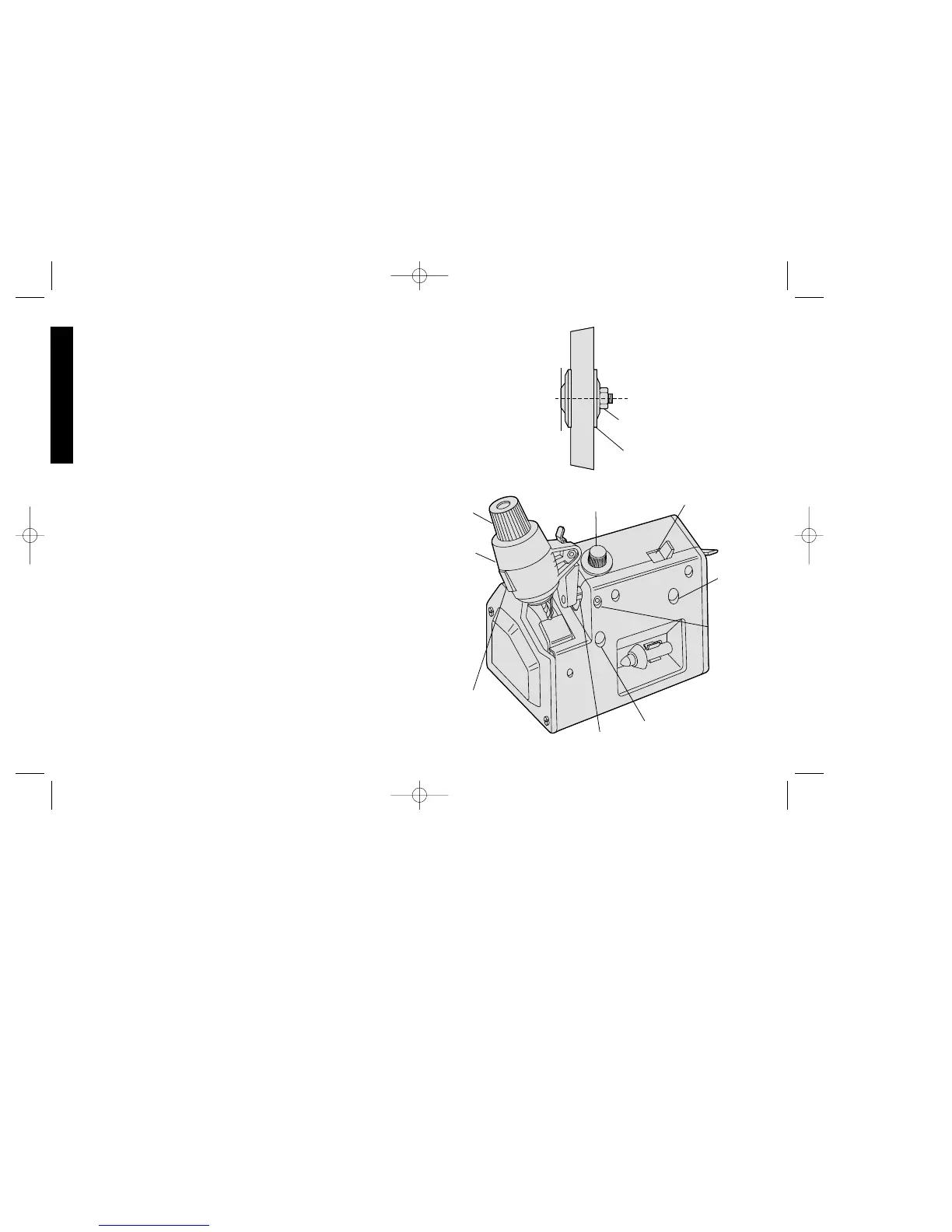
5. Attach new wheel (Fig. 24) (Note that the wheel is marked to show
which side faces out.) with clamp washer and spindle nut. Hold
wheel with a rag and tighten nut counterclockwise. Do not
overtighten.
6. Adjust guard band and finger guard to about 1/16" (1.6 mm) from
wheel (Fig. 27) and tighten adjusting screws.
7. Replace wheel cover.
8. For best results dress the new wheel with the diamond dresser.
Adjustments
FROM TIME TO TIME ADJUSTMENTS MAY BE NECESSARY DUE
TO WEAR OR SEVERE HANDLING OF THE UNIT DURING
SHIPMENT OR MOVEMENT FROM PLACE TO PLACE. SHOULD
ADJUSTMENTS BECOME NECESSARY, THE FOLLOWING
PROCEDURES SHOULD BE FOLLOWED CAREFULLY TO
INSURE PROPER AND SAFE OPERATION OF YOUR
SHARPENER.
UNPLUG TOOL BEFORE MAKING ANY ADJUSTMENTS.
1. Looseness in Pivot Rod Bearing System (Fig. 25.)
A. Set selector lever to “S” (Sharpen).
B. Position swinghead with locator approximately 1/8” (3 mm)
above wheel.
C. Loosen both front bearing gib screws until slight side play in
pivot is evident.
D. While rocking swinghead, adjust back bearing gib screw until
very slight pivoting resistance is felt. Back off screw 1/8 to 1/4
turn.
E. Adjust front bearing top and bottom gib screws evenly, while
rocking swinghead, until slight pivoting resistance is felt.
2. Latch Adjustment (Fig. 26)
A. Move swinghead to sharpening position.
English
FIG. 24
SPINDLE
NUT
CLAMP
WASHER
CHUCK
KNOB
SHARPEN/DRESS
SELECTOR
BACK
BEARING
GIB
SCREW
FRONT
BEARING
GIB
SCREW
(TOP)
FRONT BEARING GIB
SCREW (BOTTOM)
PIVOT ROD
CHUCK
RETAINING
SCREW
SWING-
HEAD
FIG. 25
FEED KNOB
RETAINING SCREW