ENGLISH
24
...................... Class II
Construction
(double insulated)
n
o
........................no load speed
n .........................rated speed
......................earthing terminal
.....................safety alert symbol
.....................visible radiation
..................... wear respiratory
protection
..................... wear eye
protection
..................... wear hearing
protection
SAVE THESE INSTRUCTIONS FOR
FUTURE USE
Motor
Be sure your power supply agrees with the nameplate
marking. Voltage decrease of more than 10% will cause loss
of power and overheating.
tools are factory tested;
if this tool does not operate, check powersupply.
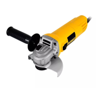
COMPONENTS (FIG. A)
WARNING: Never modify the power tool or any part
of it. Damage or personal injury couldresult.
Refer to Figure A at the beginning of this manual for a
complete list ofcomponents.
INTENDED USE
This grinder is designed for professional grinder, sander,
wire brush or cut-offapplications.
DO NOT use under wet conditions or in presence of
flammable liquids orgases.
This grinder is a professional power tool. DO NOT let
children come into contact with the tool. Supervision is
required when inexperienced operators use thistool.
ASSEMBLY AND ADJUSTMENTS
WARNING: To reduce the risk of serious personal
injury, turn unit off and disconnect it from
power source before making any adjustments or
removing/installing attachments or accessories.
An accidental start-up can causeinjury.
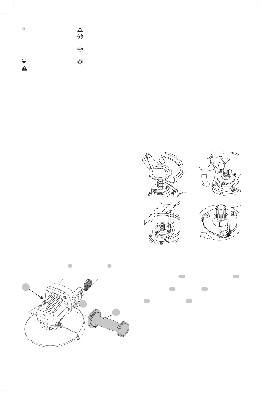
Fitting the Side Handle (Fig. B)
Tightly screw side handle
4
in one of the holes
5
of either
side of thegearbox.
Fig. B
5
5
4
Mounting and Removing the Guard
(Fig. C)
1. Align the lug on the guard with the slot in the bracket
fixed to the base of the gear case (Fig. C1).
2. Press the guard down toward the gear case, and then
rotate the guard in the direction of the arrow (Fig. C2).
3. In this position, the guard locking pin located in the
slot prevents the guard from coming loose, but allows
rotation through 105°.
To remove the guard
1. Place the tool upside down on a flatsurface.
2. Hold the tool, and using your thumb, rotate the guard
in the direction of the arrow (Fig. C3). At the same
time, using a screwdriver or other pointed instrument,
press the locking pin in the slot so the lug on the guard
comes into view (Fig. C4).
3. The locking pin does not hold the guard, and the guard
can be pushedfree.
2
Fig. C
Fitting and Removing a Grinding Disc
(Fig. A, D–E)
1. Place the tool on a table, guardup.
2. Fit the inner flange
10
correctly onto the spindle
11
(Fig.D).
3. Place the disc
12
on the flange
10
. When fitting a disc
with a raised center, make sure that the raised center
13
is facing the flange
10
.
 Loading...