ENGLISH
25
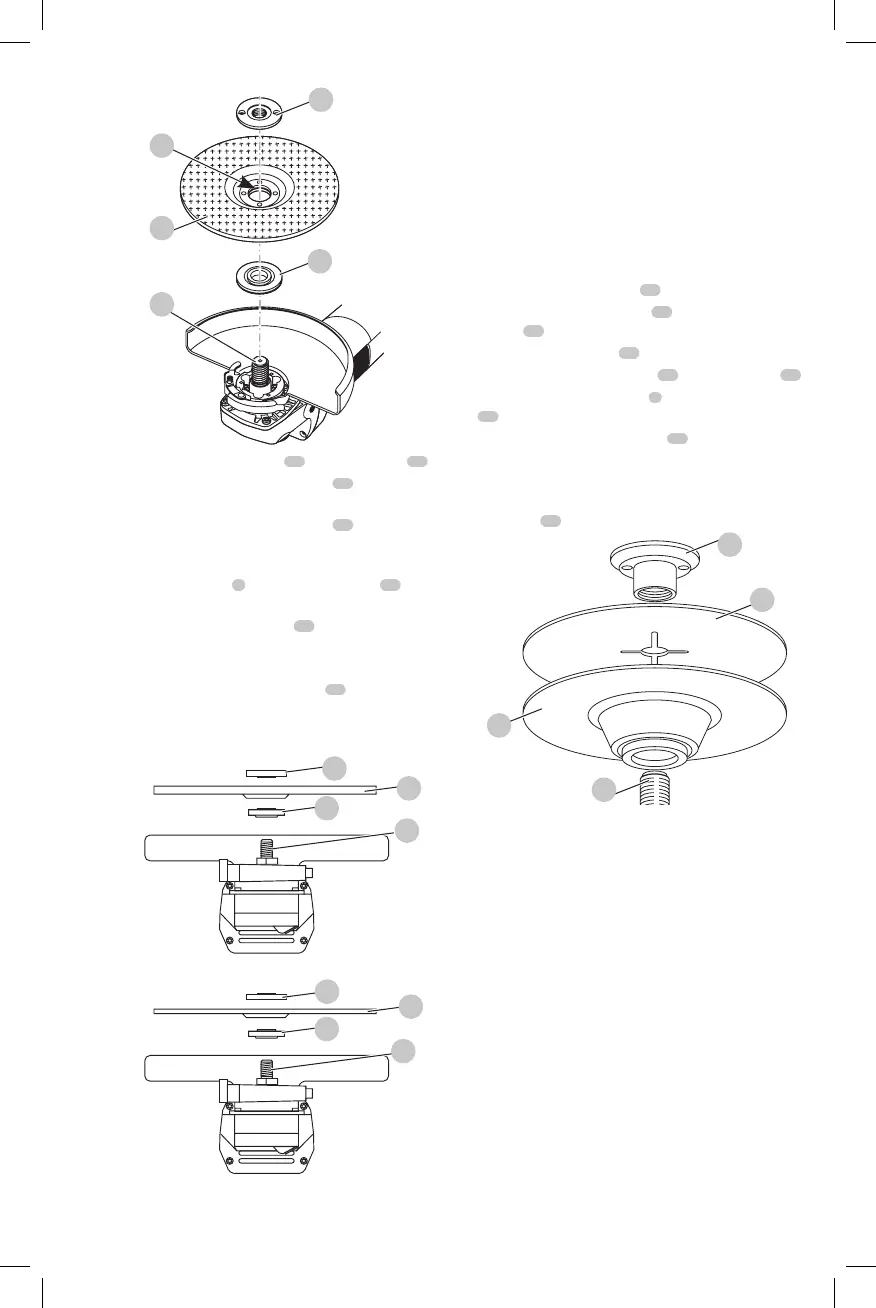
Fig. D
14
13
12
11
10
4. Screw the threaded clamp nut
14
onto the spindle
11
a. The ring on the threaded clamp nut
14
must face
towards the disc when fitting a grinding disc (Fig. E1);
b. The ring on the threaded clamp nut
14
must
face away from the disc when fitting a cutting
disc(Fig.E2).
5. Press the spindle lock
2
and rotate the spindle
11
until
it locks inposition.
6. Tighten the threaded clamp nut
14
with the two-pin
spannersupplied.
7. Release the spindlelock.
8. To remove the disc, loosen the flange
14
with the two-
pinspanner.
WARNING: Do not use a damageddisc.
Fig. E1
Fig. E2
14
12
10
14
12
10
11
11
Fitting a Wire Cup Brush
Screw the wire cup brush directly onto the spindle without
the use of the spacer and threadedflange.
Fitting and Removing a Backing
Pad/Sanding Sheet (Fig. A, D, F)
The backing pad is available at extra cost from your local
dealer or authorized servicecenter.
1. Remove the guard from thetool.
2. Remove the backing flange
10
.
3. Place the rubber backing pad
15
correctly onto the
spindle
11
.
4. Place the sanding sheet
16
on the rubber backingpad.
5. Screw the threaded clamp nut
17
onto the spindle
11
.
6. Press the spindle lock button
2
and rotate the spindle
11
until it locks inposition.
7. Tighten the threaded clamp nut
17
with the two-
pinspanner.
8. Release the spindle lock
9. To remove the rubber backing pad, loosen the threaded
clamp nut
17
wih the two-pinspanner.
Fig. F
17
16
15
11
OPERATION
WARNING: Always observe the safety instructions
and applicableregulations.
• Ensure all materials to be ground are secured
inplace.
• Apply only a gentle pressure to the tool. Do not
exert side pressure on thedisc.
• Avoid overloading. Should the tool become hot,
let it run a few minutes under no load condition to
cool theaccessory.
WARNING: To reduce the risk of serious personal
injury, turn unit off and disconnect it from
power source before making any adjustments or
removing/installing attachments or accessories.
An accidental start-up can causeinjury.
 Loading...