EasyManua.ls Logo

DeWalt dwe7491rs User Manual

DeWalt dwe7491rs
56 pages
To Next Page IconTo Next Page
Page #1 background imageLoading...
Page #1 background image
DWE7499
Heavy-Duty 10" (254 mm) Job Site Table Saw with Guard Detect
Scie de table industrielle avec de la détection de carter pour de chantier de 254mm (10po)
Sierra de banco con protector de detección de 254 mm (10 pulg.) de alta resistencia
INSTRUCTION MANUAL
GUIDE D’UTILISATION
MANUAL DE INSTRUCCIONES
INSTRUCTIVO DE OPERACIÓN, CENTROS DE SERVICIO Y PÓLIZA DE
GARANTÍA. ADVERTENCIA: LÉASE ESTE INSTRUCTIVO ANTES DE
USAR EL PRODUCTO.
Before returning this product call
1-800-4-DEWALT
IF YOU SHOULD EXPERIENCE A PROBLEM WITH YOUR D
E
WALT PURCHASE,
CALL 1-800-4-DEWALT
IN MOST CASES, A D
E
WALT REPRESENTATIVE CAN RESOLVE
YOUR PROBLEM OVER THE PHONE.
IF YOU HAVE A SUGGESTION OR COMMENT, GIVE US A CALL.
YOUR FEEDBACK IS VITAL TO THE SUCCESS OF D
E
WALT’S QUALITY
IMPROVEMENT PROGRAM.
Questions? Visit us at www.dewalt.com
Des questions ? Rendez nous visite à www.dewalt.com
¿Tiene preguntas? Visítenos en www.dewalt.com
Question and Answer IconNeed help?

Do you have a question about the DeWalt dwe7491rs and is the answer not in the manual?

DeWalt dwe7491rs Specifications

General IconGeneral
Quantity per pack1 pc(s)

Summary

Definitions: Safety Guidelines

DANGER

Defines signal word for imminent hazard.

WARNING

Defines signal word for potential hazard.

CAUTION

Defines signal word for minor/moderate hazard.

NOTICE

Defines signal word for property damage.

General Safety Rules

Double Insulation

Explains double insulated construction and its implications.

POLARIZED PLUGS

Explains polarized plugs and their use.

Additional Safety Rules for Table Saws

SAW BLADE GUARD ASSEMBLY, ANTI-KICKBACK ASSEMBLY AND RIVING KNIFE

Saw Blade Guard Assembly, Anti-Kickback Assembly and Riving Knife

Describes the function and components of the guarding system.

KICKBACKS

How to Avoid Them and Protect Yourself from Possible Injury

Provides guidance on preventing kickbacks.

Specifications

Amperes

Specifies the amperage rating of the tool.

Table Size

Provides the dimensions of the saw table.

Miter Angle

Specifies the range of miter angles.

Bevel Angle

Specifies the range of bevel angles.

Blade Size

Indicates the required blade diameter.

Max. Cut Depth, 0° Bevel

States the maximum cutting depth at 0 degrees.

Max. Cut Depth, 45° Bevel

States the maximum cutting depth at 45 degrees.

RPM, no load

Provides the no-load speed of the motor.

Unpacking (Fig. 1)

Unpacking (Fig. 1)

Instructions for unpacking the saw.

FEATURES (Fig. 2, 3)

FEATURES (Fig. 2, 3)

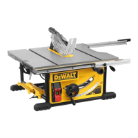
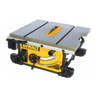
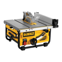
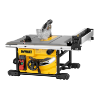
Identifies and describes the main parts of the saw.

INTENDED USE

INTENDED USE

Describes the proper applications for the table saw.

ASSEMBLY

Install and lock throat plate

Step for installing the throat plate.

Attach the rip fence

Step for attaching the rip fence.

Position the blade guard assembly

Step for positioning the blade guard.

Attach anti-kickback assembly to the guard assembly

Step for attaching the anti-kickback assembly.

ATTACHING/REPLACING THE BLADE (FIG. 2, 4)

ATTACHING/REPLACING THE BLADE (FIG. 2, 4)

Instructions for installing or removing the saw blade.

POSITIONING THE BLADE GUARD ASSEMBLY/RIVING KNIFE (FIG. 5, 6)

POSITIONING THE BLADE GUARD ASSEMBLY/RIVING KNIFE (FIG. 5, 6)

Guidance on placing the blade guard and riving knife.

TO ASSEMBLE THE THROAT PLATE (FIG. 8)

TO ASSEMBLE THE THROAT PLATE (FIG. 8)

Steps for assembling the throat plate.

TO REMOVE THE THROAT PLATE

TO REMOVE THE THROAT PLATE

Instructions for removing the throat plate.

ASSEMBLING THE RIP FENCE (FIG. 11-13)

ASSEMBLING THE RIP FENCE (FIG. 11-13)

Steps for assembling the rip fence.

ADJUSTING THE RIP SCALE (FIG. 12, 14)

ADJUSTING THE RIP SCALE (FIG. 12, 14)

Instructions for adjusting the rip scale.

ANTI-KICKBACK ASSEMBLY (FIG. 15, 16)

ANTI-KICKBACK ASSEMBLY (FIG. 15, 16)

Instructions for installing the anti-kickback assembly.

Bench Mounting

Bench Mounting

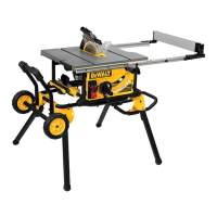
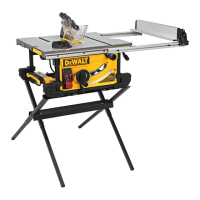
Guidance on securely mounting the table saw.

Connecting Saw to Power Source

Connecting Saw to Power Source

Instructions for connecting the saw to electricity.

ADJUSTMENTS

RAIL LOCK ADJUSTMENT (FIG. 2, 17)

Adjusting the rail lock for the fence.

BEVEL STOP AND POINTER ADJUSTMENT (FIG. 19, 20)

Adjusting the bevel angle stop and pointer.

MITER GAUGE ADJUSTMENT (FIG. 2)

Adjusting the miter gauge.

BLADE ALIGNMENT ADJUSTMENT (FIG. 18)

Aligning the blade parallel to the miter slot.

FENCE ALIGNMENT ADJUSTMENT (FIG. 2, 21)

Aligning the fence parallel to the blade.

POSITION 1 FENCE ALIGNMENT (FIG. 21)

Specific fence alignment for position 1.

POSITION 2 FENCE ALIGNMENT (FIG. 22, 23)

Specific fence alignment for position 2.

ALIGNING RIVING KNIFE TO BLADE (FIG. 24)

ALIGNING RIVING KNIFE TO BLADE (FIG. 24)

Steps to align the riving knife with the blade.

Saw Blades (Fig. 25)

Saw Blades (Fig. 25)

Information about saw blades.

Splitter and Riving Knife Selection (Fig. 26-28)

Splitter and Riving Knife Selection (Fig. 26-28)

Guidance on selecting the correct splitter and riving knife.

Kickback

Kickback

Defines kickback and its causes.

OPERATION

OPERATION

General operational safety and checks.

On-Off Switch (Fig. 29)

On-Off Switch (Fig. 29)

Operation of the power switch.

LOCK OFF FEATURE INSTRUCTIONS

LOCK OFF FEATURE INSTRUCTIONS

Instructions for using the lock-off feature.

Guard Detect Operation (Fig 29)

Guard Detect Operation (Fig 29)

Explanation of the guard detection system.

Guard Operating Feature (Fig. 30)

Guard Operating Feature (Fig. 30)

How the guard operates.

Rip Fence Operation (Fig. 31-32)

Rip Fence Operation (Fig. 31-32)

How to operate the rip fence.

WORK SUPPORT EXTENSION/NARROW RIPPING FENCE

WORK SUPPORT EXTENSION/NARROW RIPPING FENCE

Description of the extended work support/narrow ripping fence.

Ripping (Fig. 33)

Ripping (Fig. 33)

Instructions and safety for ripping operations.

Ripping Small Pieces (Fig. 34)

Ripping Small Pieces (Fig. 34)

Techniques for safely ripping small pieces.

Narrow Rip Auxiliary Fence (Fig. 35, 36)

Narrow Rip Auxiliary Fence (Fig. 35, 36)

Instructions for constructing and using the narrow rip auxiliary fence.

Push Block (Fig. 36, 37)

Push Block (Fig. 36, 37)

Instructions for constructing and using a push block.

Bevel Ripping

Bevel Ripping

How to perform ripping at a bevel angle.

Crosscutting

Crosscutting

Instructions and safety for crosscutting operations.

Bevel Crosscutting

Bevel Crosscutting

How to perform crosscutting at a bevel angle.

Mitering (Fig. 40)

Mitering (Fig. 40)

Instructions for performing miter cuts.

Miter Gauge Operation

Miter Gauge Operation

How to set and use the miter gauge.

COMPOUND MITERING

COMPOUND MITERING

Instructions for performing compound miter cuts.

Dado Cutting

Dado Cutting

Procedures and precautions for dado cuts.

Featherboard Construction (Fig. 41, 42)

Featherboard Construction (Fig. 41, 42)

How to build featherboards for workpiece support.

Dust Collection (Fig. 43)

Dust Collection (Fig. 43)

Instructions for connecting and clearing dust collection.

Motor Overload and Power Loss Reset Switch

Motor Overload and Power Loss Reset Switch

Explanation of the motor overload and reset function.

Lubrication (Fig. 44)

Lubrication (Fig. 44)

Guidance on lubricating the saw's components.

STORAGE (Fig. 45-50)

STORAGE (Fig. 45-50)

Instructions for storing the saw and its accessories.

MAINTENANCE

Cleaning

Procedures for cleaning the tool.

Accessories

Accessories

Information on recommended accessories.

Repairs

Repairs

Guidance on obtaining repair services.

Register Online

Register Online

Instructions for product registration.

Three Year Limited Warranty

Three Year Limited Warranty

Details of the product warranty.

1 YEAR FREE SERVICE

Information about the free service period.

90 DAY MONEY BACK GUARANTEE

Details of the money-back guarantee.

Push Stick Pattern

Push Stick Pattern

Pattern and instructions for making a push stick.

Related product manuals