9
ENGLISH
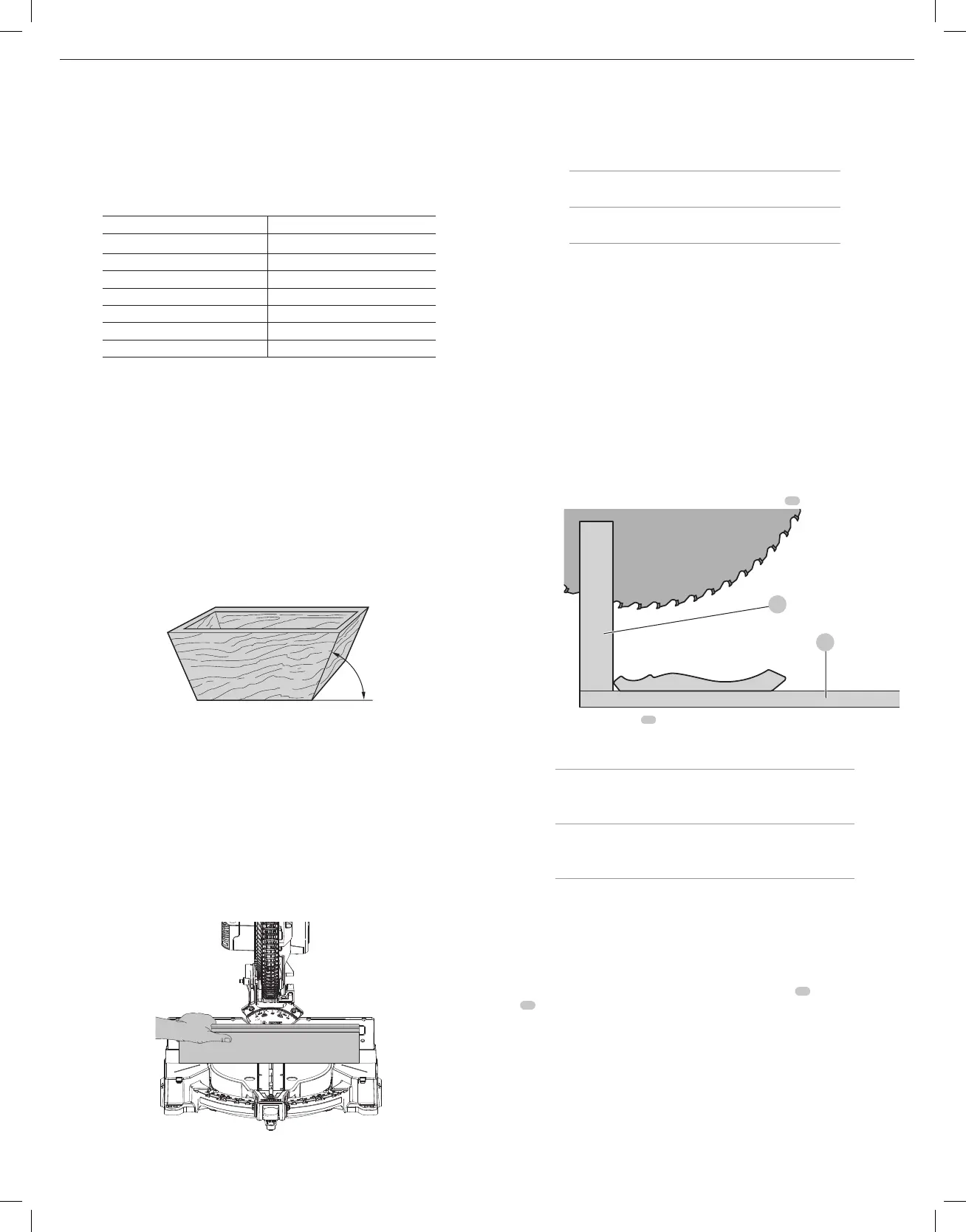
Cutting Trim Molding And Other Frames (Fig.P)
Sketch 2 in FigureP shows a joint made by setting the miter arm at 45º to miter the two boards
to form a 90º corner. To make this type of joint, set the bevel adjustment to zero and the miter
arm to 45º. Once again, position the wood with the broad flat side on the table and the narrow
edge against thefence.
The two sketches in FigureP are for four-sided objectsonly.
As the number of sides changes, so do the miter and bevel angles. The chart below gives the
proper angles for a variety ofshapes.
– EXAMPLES –
NUMBER OF SIDES MITER OR BEVEL ANGLE
4 45°
5 36°
6 30°
7 25.7°
8 22.5°
9 20°
10 18°
The chart assumes that all sides are of equal length. For a shape that is not shown in the chart,
use the following formula: 180º divided by the number of sides equals the miter (if the material is
cut vertically) or bevel angle (if the material is cut laying flat).
Cutting Compound Miters (Fig.Q)
A compound miter is a cut made using a miter angle and a bevel angle at the same time. This is
the type of cut used to make frames or boxes with slanting sides like the one shown in FigureQ.
NOTE: If the cutting angle varies from cut to cut, check that the bevel lock knob and the miter
lock handle are securely locked. These must be locked after making any changes in bevel
ormiter.
The chart at the end of this manual (Table 1) will assist you in selecting the proper bevel and
miter settings for common compound miter cuts. To use the chart, select the desired angleA
(Fig.Q) of your project and locate that angle on the appropriate arc in the chart. From that point
follow the chart straight down to find the correct bevel angle and straight across to find the
correct miterangle.
Fig. Q
Angle “A”
Set your saw to the prescribed angles and make a few trial cuts. Practice fitting the cut pieces
together until you develop a feel for this procedure and feel comfortable withit.
Example: To make a 4-sided box with 26º exterior angles (Angle A, Fig.Q), use the upper right arc.
Find 26° on the arc scale. Follow the horizontal intersecting line to either side to get miter angle
setting on saw (42°). Likewise, follow the vertical intersecting line to the top or bottom to get the
bevel angle setting on the saw (18°). Always try cuts on a few scrap pieces of wood to verify the
settings on thesaw.
Cutting Base Molding (Fig. R)
ALWAYS MAKE A DRY RUN WITHOUT POWER BEFORE MAKING ANYCUTS.
Straight 90° cuts:
Position the wood against the fence and hold it in place as shown in FigureR. Turn on the saw,
allow the blade to reach full speed and lower the arm smoothly through thecut.
Fig. R
Cutting Base Molding up to 6.75" (171 mm) Vertically Against
the Fence (Fig. R)
Position material as shown in FigureR.
All cuts should be made with the back of the molding against the fence and with the bottom of
the molding against thetable.
Inside corner Outside corner
Left side
1. Miter left 45°
2. Save left side of cut
1. Miter right 45°
2. Save left side of cut
Right side
1. Miter right 45°
2. Save right side of cut
1. Miter left 45°
2. Save right side of cut
Material up to 6.5"(165mm) can be cut as describedabove.
Cutting Crown Molding
Your miter saw is better suited to the task of cutting crown molding than any tool made. In order
to fit properly, crown molding must be compound mitered with extremeaccuracy.
The two flat surfaces on a given piece of crown molding are at angles that, when added together,
equal exactly 90°. Most, but not all, crown molding has a top rear angle (the section that fits flat
against the ceiling) of 52° and a bottom rear angle (the part that fits flat against the wall) of38°.
Your miter saw has special pre-set miter latch points at 31.6° left and right for cutting crown
molding at the proper angle. There is also a mark on the bevel scale at 33.9°.
The chart below gives the proper settings for cutting crown molding. (The numbers for the miter
and bevel settings are very precise and are not easy to accurately set on your saw.) Since most
rooms do not have angles of precisely 90º, you will have to fine tune your settingsanyway.
PRETESTING WITH SCRAP MATERIAL IS EXTREMELY IMPORTANT!
Instructions for Cutting Crown Molding Laying Flat and Using
the Compound Features (Fig. A, S)
1. Molding laying with broad back surface down flat on saw table
16
.
Fig. S
10
16
2. Top of molding against fence
10
.
3. The settings below are for all standard (U.S.) crown molding with 52° and 38°angles.
Inside corner Outside corner
Left side
1. Bevel left 33.9°
2. Miter table set at right 31.62°
3. Save left end of cut
1. Bevel right 33.9°
2. Miter table set at left 31.62°
3. Save left end of cut
Right side
1. Bevel right 33.9°
2. Miter table set at left 31.62°
3. Save right end of cut
1. Bevel left 33.9°
2. Miter table set at right 31.62°
3. Save right end of cut
When setting bevel and miter angles for all compound miters, remember that:
The angles presented for crown moldings are very precise and difficult to set exactly. Since they
can easily shift slightly and very few rooms have exactly square corners, all settings should be tested
on scrapmolding.
PRETESTING WITH SCRAP MATERIAL IS EXTREMELY IMPORTANT!
Alternative Method for Cutting Crown Molding (Fig. T)
Place the molding on the table at an angle between the sliding fence
10
and the saw
table
16
, as shown in FigureT. Use of the crown molding fence accessory (DW7084) is highly
recommended because of its degree of accuracy and convenience. The crown molding fence
accessory is available for purchase from your localdealer.
The advantage to cutting crown molding using this method is that no bevel cut is required.
Minute changes in the miter angle can be made without affecting the bevel angle. This way,
when corners other than 90° are encountered, the saw can be quickly and easily adjusted for
them. Use the crown molding fence accessory to maintain the angle at which the molding will
be on thewall.

 Loading...