5
ENGLISH
ASSEMBLY AND ADJUSTMENTS
WARNING: To reduce the risk of serious personal injury, turn unit off and disconnect
it from power source before making any adjustments or removing/installing
attachments or accessories. An accidental start-up can causeinjury.
NOTE: Your miter saw is fully and accurately adjusted at the factory at the time of manufacture.
If readjustment due to shipping and handling or any other reason is required, follow the steps
below to adjust yoursaw.
Once made, these adjustments should remain accurate. Take a little time now to follow these
directions carefully to maintain the accuracy of which your saw iscapable.
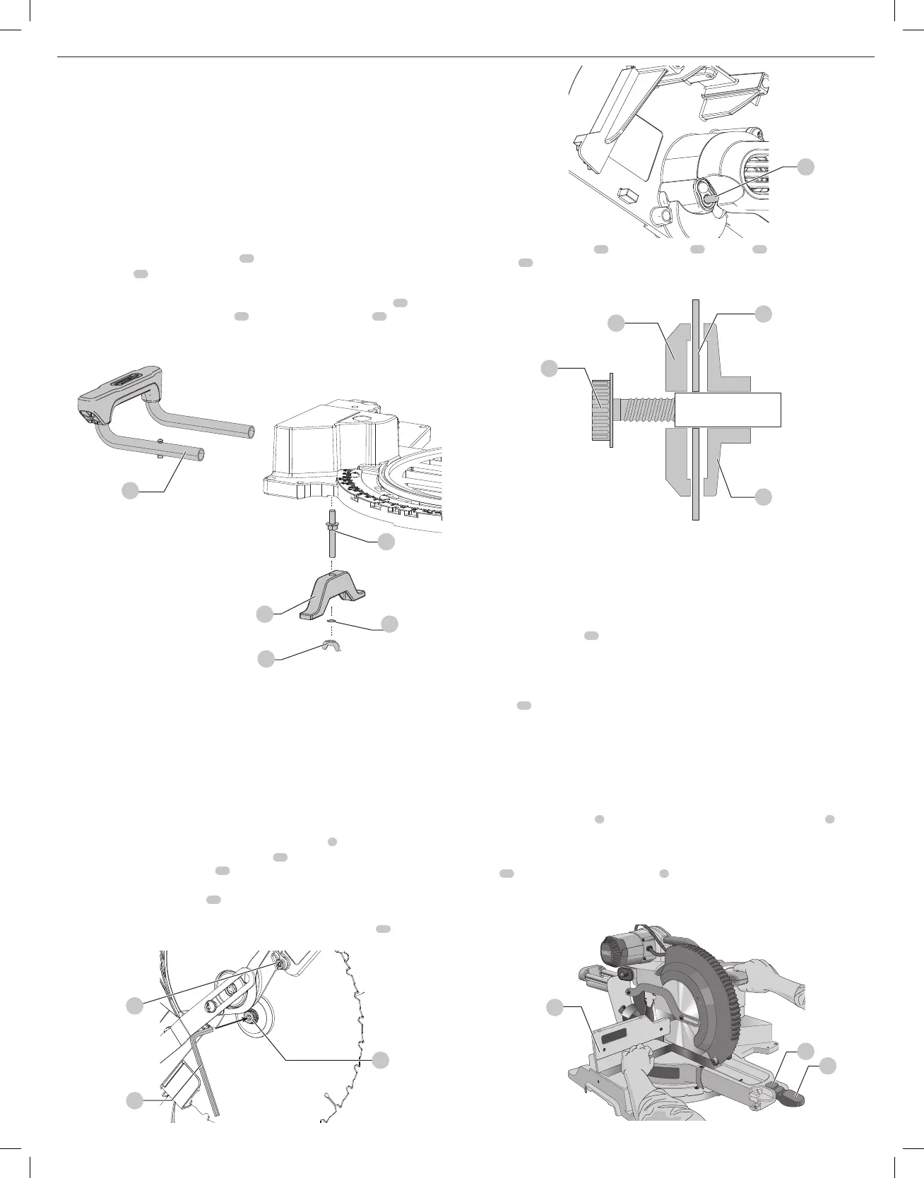
Assembling the Base Extensions (Fig. C)
WARNING: Base extensions must be assembled to both sides of the saw's base before using
the saw.
1. Locate the preassembled threaded stud
51
underneath the saw’sbase.
2. The extension
32
should be oriented as shown in the illustration, sliding fully rearward in the
U-shaped supports.
3. Clamp the extension’s rods against the miter saw base by inserting the clamp
52
over the
threaded stud, followed by the washer
53
, and tightening the wing nut
34
. Ensure the
extension is secure by pulling on the extension to verify no movement.
4. Repeat steps 1 through 3 on the other side.
32
Fig. C
52
34
53
51
Changing or Installing a New Saw Blade (Fig.A, D–F)
WARNING: To reduce the risk of serious personal injury, turn off the tool and
disconnect it from the power source before attempting to move it, change
accessories or make anyadjustments.
CAUTION:
• Never depress the spindle lock button while the blade is under power orcoasting.
• Do not cut ferrous metal (containing iron or steel) or masonry or fiber cement product
with this mitersaw.
Removing the Blade
1. Unplug thesaw.
2. Raise the arm to the upper position and raise the lower guard
4
as far aspossible.
3. Loosen, but do not remove guard bracket screw
54
until the bracket can be raised far
enough to access the blade screw
35
. Lower guard will remain raised due to the position of
the guard bracketscrew.
4. Depress the spindle lock button
19
while carefully rotating the saw blade by hand until the
lockengages.
5. Keeping the button depressed, use the other hand and the blade wrench
37
provided to
loosen the blade screw. (Turn clockwise, left-hand threads.)
Fig. D
54
37
35
Fig. E
19
6. Remove the blade screw
(
35
)
, outer blade clamp
(
38
)
, and blade
(
39
)
. The inner clamp
clamp
(
41
and if used, the 1" (25.4 mm) blade adapter, may be left on thespindle.
NOTE: For blades with a blade hole of 5/8" (15.88 mm), the 1" (25.4 mm) blade adapter is
notused.
Fig. F
35
38
39
41
Installing a Blade
1. Unplug thesaw.
2. With the arm raised, the lower guard held open and the guard bracket raised, place the blade
on the spindle, onto the blade adapter [if using a blade with a 1" (25.4 mm) diameter blade
hole] and against the inner blade clamp with the teeth at the bottom of the blade pointing
toward the back of thesaw.
3. Assemble the outer blade clamp onto thespindle.
4. Install the blade screw
35
and, engaging the spindle lock, tighten the screw firmly with the
blade wrench provided. (Turn counterclockwise, left-hand threads.)
NOTE: When using blades with a 5/8" (15.88 mm) diameter blade hole, the blade adapter
will not be used and should be stored in a safe place for futureuse.
5. Return the guard bracket to its original position and firmly tighten the guard bracket
screw
54
to hold bracket inplace.
WARNING:
• The guard bracket must be returned to its original position and the screw
tightened before activating thesaw.
• Failure to do so may allow the guard to contact the spinning saw blade resulting
in damage to the saw and severe personalinjury.
Miter Scale Adjustment (Fig.A, G)
Unlock the miter lock handle
5
and swing the miter arm until the miter latch button
6
locks
it at the 0° miter position. Do not lock the miter lock handle. Place a square against the saw’s
fence and blade, as shown. (Do not touch the tips of the blade teeth with the square. To do
so will cause an inaccurate measure ment.) If the saw blade is not exactly perpendicular to the
fence
10
, loosen the four miter scale screws
8
that hold the miter scale and move the miter
lock handle and the scale left or right until the blade is perpendicular to the fence, as measured
with the square. Retighten the four screws. Pay no attention to the reading of the miter pointer
at thistime.
Fig. G
6
10
5

 Loading...