7
ENGLISH
Depth Stop (Fig. A)
The depth stop
24
allows the depth of cut of the blade to be limited. The stop is useful for
applications such as grooving and tall vertical cuts. Rotate the depth stop forward and adjust the
depth adjustment screw
28
to set the desired depth of cut. To secure the adjustment, tighten
the wing nut
20
. Rotating the depth stop to the rear of the saw will bypass the depth stop
feature. If the depth adjustment screw is too tight to loosen by hand, the provided blade wrench
can be used to loosen thescrew.
Lock Down Pin (Fig. A)
WARNING: The lock down pin should be used only when carrying or storing the saw. NEVER
use the lock down pin for any cuttingoperation.
To lock the saw head in the down position, push the saw head down, push the lock down pin
17
in and release the saw head. This will hold the saw head safely down for moving the saw from
place to place. To release, press the saw head down and pull the pinout.
Automatic Electric Brake
Your saw is equipped with an automatic electric blade brake which stops the saw blade within
5seconds of trigger release. This is notadjustable.
On occasion, there may be a delay after trigger release to brake engagement. On rare occasions,
the brake may not engage at all and the blade will coast to astop.
If a delay or “skipping” occurs, turn the saw on and off 4 or 5 times. If the condition persists, have
the tool serviced by an authorized D
WALT servicecenter.
Always be sure the blade has stopped before removing it from the kerf. The brake is not a
substitute for guards or for ensuring your own safety by giving the saw your completeattention.
OPERATION
WARNING: To reduce the risk of serious personal injury, turn unit off and disconnect
it from power source before making any adjustments or removing/installing
attachments or accessories. An accidental start-up can causeinjury.
WARNING: Always use eye protection. All users and bystanders must wear eye protection
that conforms to ANSI Z87.1 (CAN/CSA Z94.3).
Plug the saw into any household 60 Hz power source. Refer to the nameplate for voltage. Be sure
the cord will not interfere with yourwork.
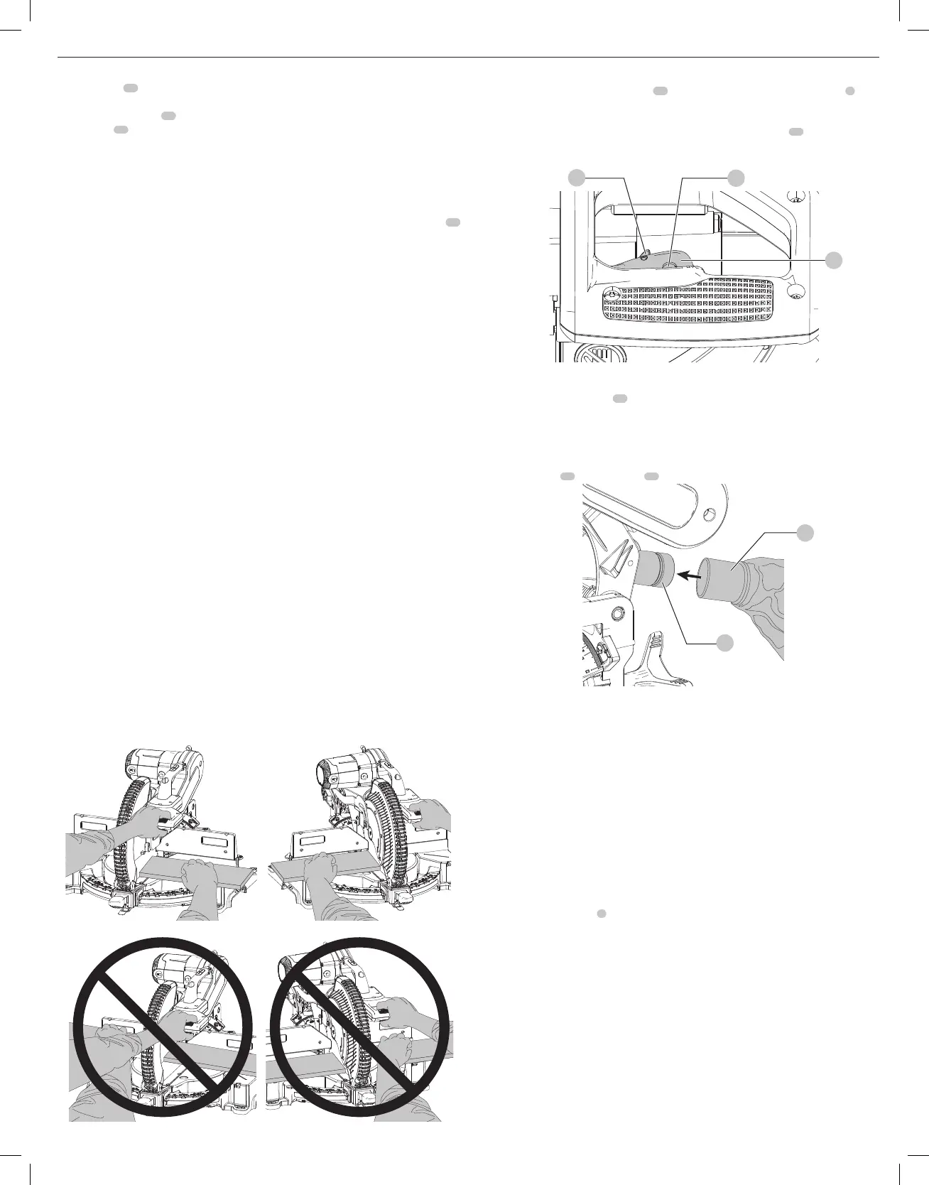
Body and Hand Position (Fig.K1–K4)
WARNING: To reduce the risk of serious personal injury, ALWAYS use proper hand position
asshown.
WARNING: To reduce the risk of serious personal injury, ALWAYS hold securely in anticipation of
a suddenreaction.
Proper positioning of your body and hands when operating the miter saw will make cutting
easier, more accurate and safer. Never place hands near cutting area. Place hands no closer than
4" (100mm) from the blade. Hold the workpiece tightly to the table and the fence when cutting.
Keep hands in position until the trigger has been released and the blade has completely stopped.
ALWAYS MAKE DRY RUNS (UNPOWERED) BEFORE FINISH CUTS SO THAT YOU CAN CHECK THE
PATH OF THE BLADE. DO NOT CROSS ARMS, AS SHOWN IN FIGUREK3.
Keep both feet firmly on the floor and maintain proper balance. As you move the miter arm
left and right, follow it and stand slightly to the side of the saw blade. Sight through the guard
louvers when following a pencilline.
Fig. K1 Fig. K2
Fig. K3 Fig. K4
Trigger Switch (Fig.L)
To turn the saw on, push the lock-off lever
40
to the left, then depress the trigger switch
1
. The
saw will run while the switch is depressed. Allow the blade to spin up to full operating speed
before making the cut. To turn the saw off, release the switch. Allow the blade to stop before
raising the saw head. There is no provision for locking the switch on. A hole
50
is provided in the
trigger for insertion of a padlock to lock the switchoff.
Always be sure the blade has stopped before removing it from thekerf.
Fig. L
40
1
50
Dust Extraction (Fig.M)
Your saw has a built-in dust port
15
that allows either the supplied dust bag or a shop vacuum
system to beconnected.
NOTE: This saw has a dust port equipped with an AirLock
TM
fitting, which is a universal system
that connects tools to dust extraction shrouds to minimize cleanup on thejobsite.
To Attach the Dust Bag
1. Fit the dust bag
56
to the dust port
15
as shown in FigureM.
56
Fig. M
15
Through-Cutting Operations (Fig. A)
If the slide feature is not used, ensure the saw head is pushed back as far as possible and the
rail lock knob is tightened. This will prevent the saw from sliding along its rails as the workpiece
isengaged.
NOTE: Although this saw will cut wood and many non-ferrous materials, we will limit our
detailed discussion to the cutting of wood only. The same guidelines apply to the other
materials. DO NOT CUT FERROUS (IRON AND STEEL) MAT ERIALS OR MASONRY WITH THIS SAW.
Do not use any abrasiveblades.
NOTE: Refer to Guard Actuation and Visibility in the Assembly and Adjustments section for
important information about the lower guard beforecutting.
Crosscuts (Fig. A, N)
A crosscut is made by cutting wood across the grain at any angle. A straight crosscut is made
with the miter arm at the zero degree position. Set and lock the miter arm at zero, hold the wood
firmly on the table and against the fence. With the rail lock knob tightened, turn on the saw by
squeezing the trigger switch
1
shown in FigureA.
When the saw comes up to speed (about 1 second) lower the arm smoothly and slowly to cut
through the wood. Let the blade come to a full stop before raising arm.
When cutting anything larger than a 2 x 8 (51 x 203mm [2 x 6 (51 x 152) at 45º miter]) use an
out-down-back motion with the rail lock knob loosened. Pull the saw out, toward you, lower the
saw head down toward the workpiece, and slowly push the saw back to complete the cut. Do
not allow the saw to contact the top of the workpiece while pulling out. The saw may run toward
you, possibly causing personal injury or damage to theworkpiece.
Cutting of multiple pieces is not recommended but can be done safely by ensuring that each
piece is held firmly against the table and fence.
NOTE: To provide greater crosscut capacity with reduced stroke, the blade on the DWS779
extends deeper into the table. As a result, a greater lifting force on the workpiece may be
experienced during thecut.

 Loading...