6
ENGLISH
Guard Actuation and Visibility (Fig. A, Y)
CAUTION: Pinch Hazard. To reduce the risk of injury, keep thumb underneath the handle
when pulling the handle down. The lower guard will move up as the handle is pulled down
which could causepinching.
The lower guard
4
on your saw has been designed to automatically uncover the blade when the
arm is brought down and to cover the blade when the arm israised.
The guard can be raised by hand when installing or removing saw blades or for inspection of the
saw. NEVER RAISE THE LOWER GUARD MANUALLY UN LESS THE BLADE ISSTOPPED.
NOTE: Certain special cuts of large material will require that you manually raise the guard. Refer
to Cutting Large Material under SpecialCuts.
The front section of the guard is louvered for visibility while cutting. Although the louvers
dramatically reduce flying debris, they are openings in the guard and safety glasses should be
worn at all times when viewing through thelouvers.
Rail Guide Adjustment (Fig. A)
Periodically check the rails
23
for any play or clearance. The right rail can be adjusted with the
rail set screw
31
shown in FigureA. To reduce clearance, use a 4 mm hex wrench and rotate the
rail set screw clockwise gradually while sliding the saw head back and forth. Reduce play while
maintaining minimum slideforce.
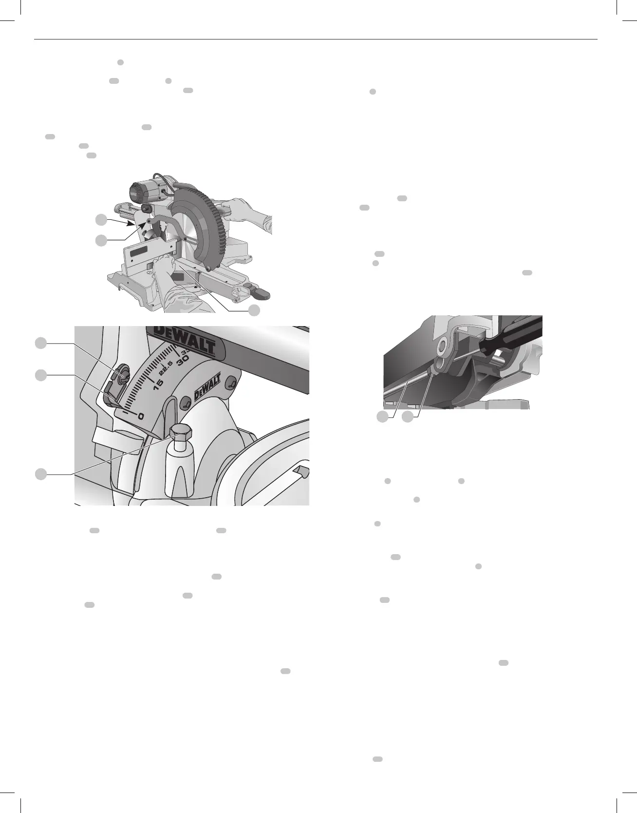
Miter Lock Adjustment (Fig. A, J)
The miter lock rod
45
should be adjusted if the table of the saw can be moved when the
miter lock handle
5
is locked (down). To adjust the miter lock, put the miter lock handle in the
unlocked (up) position. Using a 1/2” open end wrench, loosen the lock
46
nut on the miter lock
rod. Using a slotted screwdriver, tighten the miter lock rod by turning it clockwise. Turn the lock
rod until it is snug, then turn counterclockwise one turn. To ensure the miter lock is functioning
properly, re-lock the miter lock to a non-detented measurement on the miter scale – for example,
34º – and make sure the table will not rotate. Tighten locknut.
Fig. J
45 46
Controls
Your compound miter saw has several main controls, which will be discussed briefly here. For
more information on these controls, see the respective sections later in themanual.
Miter Control (Fig. A)
The miter lock handle
5
and miter latch button
6
allow you to miter your saw to 60° right and
50° left. To miter the saw, lift the miter lock handle, push the miter latch button and set the miter
angle desired on the miter scale
7
. Push down on the miter lock handle to lock the miterangle.
Trigger Switch (Fig. A)
The trigger switch
1
turns your saw on and off. A hole is provided in the trigger for insertion of a
padlock to secure thesaw.
Miter Latch Override (Fig. A)
The miter latch override
22
allows your saw to override the common stop angles. To override
the common stop angles, push the miter latch button
6
and flip the miter latch override lever to
the verticalposition.
Bevel Lock Knob (Fig. A)
The bevel lock knob
11
allows you to bevel the saw 49° left or right. To adjust the bevel setting,
turn the knob counterclockwise. The saw head bevels easily to the left or to the right once the 0°
bevel override knob is pulled. To tighten, turn the bevel lock knobclockwise.
0° Bevel Override (Fig. A)
The bevel stop override allows you to bevel the saw to the right past the 0°mark.
When engaged, the saw will automatically stop at 0° when brought up from the left. To
temporarily move past 0° to the right, pull the bevel lock knob
11
. Once the knob is released, the
override will be reengaged. The bevel lock knob can be locked out by twisting the knob 180°.
When at 0°, the override locks in place. To operate the override, bevel the saw slightly to theleft.
45° Bevel Stop Override (Fig. A)
The bevel stop overrides are held secure with their attachment screw to prevent inadvertent
movement. Use the bit on the blade wrench to loosen the attachment screw. This allows the
slides, to be pulled outward and the saw head to pivot past the 45º mark. Be sure to retighten the
attachment screw when finished.
Rail Lock Knob (Fig. A)
The rail lock knob
29
allows you to lock the saw head firmly to keep it from sliding on the rails.
This is necessary when making certain cuts or when transporting thesaw.
Miter Pointer Adjustment (Fig.A)
Unlock the miter lock handle
5
to move the miter arm to the zero position. With the miter lock
handle unlocked, allow the miter latch to snap into place as you rotate the miter arm to zero.
Observe the miter pointer
30
and miter scale
7
shown in FigureA. If the pointer does not
indicate exactly zero, loosen the miter pointer screw
26
holding the pointer in place, reposition
the pointer and tighten thescrew.
Bevel Square to Table (Fig.A, H, I)
To align the blade square to the table
16
, lock the arm in the down position with the lock down
pin
17
. Place a square against the blade, ensuring the square is not on top of a tooth. Loosen the
bevel lock knob
11
and ensure the arm is firmly against the 0° bevel stop. Rotate the the 0° bevel
adjustment screw
42
with the 1/2” blade wrench as necessary so that the blade is at 0° bevel to
thetable.
Fig. H
16
17
11
Fig. I
43
44
42
Bevel Pointer (Fig.I)
If the bevel pointer
43
does not indicate zero, loosen the screw
44
that holds it in place and
move the pointer as necessary. Ensure the 0° bevel is correct and the bevel pointers are set before
adjusting any other bevel anglescrews.
Adjusting the Bevel Stop to 45° Left or Right (Fig.A, I)
To adjust the right 45° bevel angle, loosen the bevel lock knob
11
and pull the 0° bevel stop to
override the 0° bevel stop. When the saw is fully to the right, if the bevel pointer does not indicate
exactly 45°, turn the left 45° bevel adjustment screw
33
(Fig. A) with the 1/2” blade wrench until
the bevel pointer
43
indicates 45°.
To adjust the left 45° bevel stop, first loosen the bevel lock knob and tilt the head to the left. If the
bevel pointer does not indicate exactly 45°, turn the right 45° bevel adjustment screw until the
bevel pointerreads 45°.
Fence Adjustment (Fig.A)
In order that the saw can bevel to many bevel positions, one of the fences may have to be
adjusted to provide clearance. To adjust each fence, loosen the fence adjustment knob
14
and slide the fence outward. Make a dry run with the saw turned off and check for clearance.
Adjust the fence to be as close to the blade as practical to provide max imum workpiece support,
without interfering with arm up and down movement. Tighten the fence adjustment knob
securely. When the bevel operations are complete, don’t forget to relocate thefence.
For certain cuts, it may be desirable to bring the fences closer to the blade. To use this feature,
back the fence adjustment knobs out two turns and move the fences closer to the blade past the
normal limit, then tighten the fence adjustment knobs to keep the fences in this location. When
using this feature, make a dry cut first to ensure the blade does not contact thefences.
NOTE: The tracks of the fences can become clogged with sawdust. If you notice that they are
becoming clogged, use a brush or some low pressure air to clear the guidegrooves.

 Loading...